Category: Datacenter Design

Lab V ( Nexus7k, Overlay Transport Virtualization )

OTV: Overlay Transport Virtualization

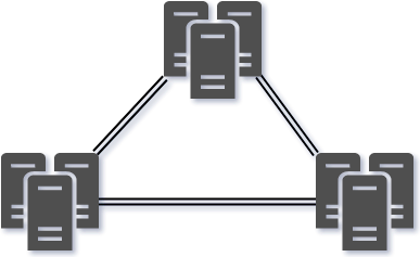
OTV(Overlay Transport Virtualization) is a technology that provide layer2 extension capabilities between different data centers.
I
n its most simplest form OTV is a new DCI (Data Center Interconnect) technology that routes MAC-based information by encapsulating traffic in normal IP packets for transit.

  • Transparent workload mobility
  • Business resiliency
  • Superior computing resource efficiencies
DescriptionConfig
Overlay InterfaceLogical OTV Tunnel interfaceinterface Overlay1
OTV Join InterfaceThe physical link or port-channel that you use to route upstream towards the datacenter interconnectotv join-interface Ethernet2/1
OTV Control GroupMulticast address used to discover the remote sites in the control plane.otv control-group 224.100.100.100
OTV Data GroupUsed for tunneling multicast traffic over the OTV in the dataplaneotv data-group 232.1.2.0/24
Extend VLANsVLANs that will be tunneled over OTV.otv extend-vlan 100
Site VLANUsed to synchronize the Authoritative Edge Device (AED) role within an OTV site. otv site-vlan 999
Site IdentifierShould be unique per Datacenter. Used in AED Election.otv site-identifier 0x1

References:

Cisco: OTV Quick Start Guide

Cisco: NX-OS OTV Configuration Guide

Cisco: OTV Best Practices

Cisco: OTV Whitepaper

OTV Encapsulation

OTV adds a further 42 bytes on all packets traveling across the overlay network. The OTV Edge device removes the CRC and 802.1Q fields from the original Layer2 frame. It then adds an OTV Shim Header which includes this 802.1Q field (this includes the priority P-bit value) and the Overlay ID information. It also includes an external IP header for the transport network. All OTV packets have Don’t Fragment (DF) bit set to 1 in the external IP header.

(more…)

Datacenter Design VI ( SDN )

Software Defined Networking

  • Advantages SDN
    • Automatic Infrastructure Provisioning
    • Multi-tenant enviornments
    • Flexible Placement of servers ( Mobility )
    • Health monitoring of applications
    • Application to NET ( Southbound ) and NET to application ( Northbound ) communication
  • Cisco’s SDN implementation: Application Centric Infrastructure ( ACI )

Three key ingredients for ACI

  • Nexus 9000 series / 9300 / 9500.
  • Aplication Policy Infrastructure Controller ( APIC ).
    • Cisco recommends a minimum of three APIC servers.
  • Policy Model ( “What talks to what and how” ).

(more…)

Datacenter Design IV ( VPC , MEC, Fabric Extenders )

What is a vPC (virtual Port Channel)

  • Nexus series Network Virtualisation Technology.
  • “Lightweight” VSS – Combine ports, not switches.
  • Links on different switches to appear as the same device.
  • Downstream device can be anything supoprting 802.3ad (LACP).
  • Commonly called Multi Chassis Etherchannel ( MEC ).

(more…)

Datacenter Design III (STP, High availability, Failover timers)

STP in the datacenter

STP logical interfaces maximum

  • RSTP / MST reach topology maximus. Switch specs logical / virtual interfaces.  (6500/ 6748)
    • Logical interfaces == ((trunk ports * vlans ) + non-trunk interfaces)
    • Virtual interfaces ( Per line card ) = (( trunk ports * vlans ))
    • verify with ‘show spantree sum total

Example logical interfaces:

6500 Chassis:

  • 120 VLANS
  • 49 Access layer switches
  • 2 connections to each switch ( double uplink but with etherchannel counts as 1 logical interface )
  • 1 Cross Connect to secondary Agg Switch.
  • 30 other devices connected
    • (( 120 * 50 ) + 30 ) = 6030 Logical interface (out of 10,000 max)

Example Virtual interfaces:

Cisco 6748 Linecard

  • 120 VLANS
  • 12 Access layer switches, 4 Etherchannel-bundled connections.
    • 12 x 4 = 48 ports  ( Virtual interfaces counts every interface )
      • ( 120 * 48 ) = 5760 Virtual Interfaces (out of 1800 max)

High Availability

Nic teaming options

  • Adapter fault tolerance (AFT):  active / standby  – Two nics  One switch
  • Switch fault tolerance (SFT):  active / standby  – Two nics Two switches
  • Adaptive Load Balancing (ALB):  active / active – One IP Two Macs
  • Etherchannel – LAG

Expectations and Failover Timers

OperationFailover time
OSPF / EIGRPSubsecond
RTSP1-2 Seconds
Etherchannel1 Second
HSRP Timers3 Seconds
Service Modules1-5 Seconds
Windows TCP Stack Tolerance9 Seconds

Datacenter Design II (Blades, Scaling, Bandwidth)

Blade Server design

  • Overleg with the server team connectivity.
  • Many blade servers enter de “enterprise switch” market with an integrated switch.
  • Pass-through cabling or integrated switches.
  • Significant impact on power – cooling – weight.

Connecting the blade to the network

  • If you use the integrated blade switch, use a layer3 access layer.
  • Avoid a double Layer 2 design:
    •  [Layer 2 on the access layer] connected to a [layer 2 domain within the bladeswitch].
  • If you use passthrough, use a layer2 or layer3 access layer.

Scaling the Datacenter Architecture

(more…)

Datacenter Design I (Core, Aggregation, Access Designs)

Core

  • Not all datacenter designs needs a core layer
  • Access to aggregation, aggregation to core : 10 or 40GBps
  • CEF load balancing tuning (L3 + L4)
  • Core should run L3 only, Aggregation acts as L3/L2 boundry to access
  • Core runs OSPF / EIGRP with aggregation

Aggregration

(more…)