IS-IS – Interlevel Routing

Intermediate System to Intermediate System (IS-IS)
Intermediate System to Intermediate System (IS-IS) is a dynamic link-state routing protocol widely used in large-scale networks, especially in service provider environments. One of its features is interlevel routing, which allows communication between IS-IS levels (Level 1 and Level 2). This post explains IS-IS interlevel routing and provides configuration examples to implement it in practical scenarios.
IS-IS Lab Setup
Labs download |
Using Cisco’s Modeling Labs (CML) I build the following IS-IS topology:
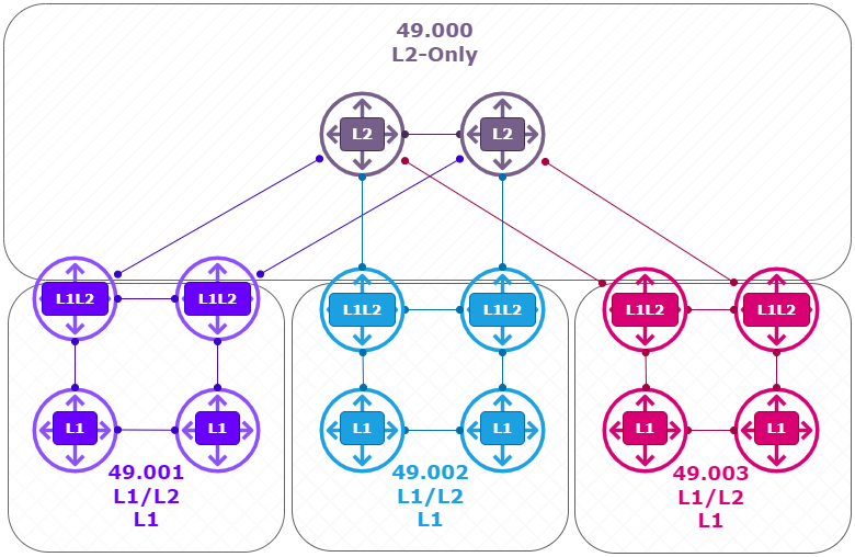
- 2 x L2 Router ( Top ) (R1, R2) running XRv with IOS-XR.
- 2 x L1L2 Router ( left ) (R3, R4) running XRv with IOS-XR.
- 2 x L1 Router ( left ) (R9, R10) running IOS with IOSv.
- 2 x L1L2 Router ( Center ) (R5, R6) running XRv with IOS-XR.
- 2 x L1 Router ( Center ) (R11, R12) running IOS with IOSv.
- 2 x L1L2 Router ( Right ) (R7, R8) running XRv with IOS-XR.
- 2 x L1 Router ( Right ) (R13, R14) running IOS with IOSv.
Logical View:
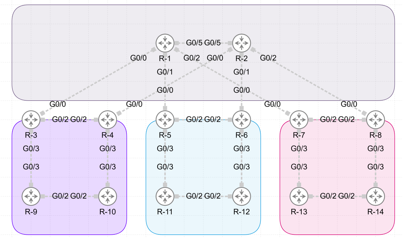
Physical View:
IP Addressing:
The point-to-point links are configured with the following IP addressing scheme:
- “10.<Lowest Router Id>.<Highest Router Id>.<Router Id>./24.”
For example the link between R1 and R 2 gives on P1: 10.1.2.1/24 and on P2: 10.1.2.2/24.
| Device | Function | Loopback address | Subnets | Image |
|---|---|---|---|---|
| R1 | L2 Router (Backbone) | 1.1.1.1/32 | G0 10.1.3.1/24 G1 10.1.5.1/24 G2 10.1.7.1/24 G5 10.1.2.1/24 | IOS XRV |
| R2 | L2 Router (Backbone) | 2.2.2.2/32 | G0 10.2.4.2/24 G1 10.2.6.2/24 G2 10.2.8.2/24 G5 10.1.2.2/24 | IOS XRV |
| R3 | L1/L2 Router | 3.3.3.3/32 | G0 10.1.3.3/24 G2 10.3.4.3/24 G3 10.3.9.3/24 | IOS XRV |
| R4 | L1/L2 Router | 4.4.4.4/32 | G0 10.2.4.4/24 G2 10.3.4.4/24 G3 10.3.10.4/24 | IOS XRV |
| R5 | L1/L2 Router | 5.5.5.5/32 | G0 10.1.5.5/24 G2 10.5.6.5/24 G3 10.5.11.5/24 | IOS XRV |
| R6 | L1/L2 Router | 6.6.6.6/32 | G0 10.2.6.6/24 G2 10.5.6.6/24 G3 10.6.12.6/24 | IOS XRV |
| R7 | L1/L2 Router | 7.7.7.7/32 | G0 10.1.7.7/24 G2 10.7.8.7/24 G3 10.7.13.7/24 | IOS XRV |
| R8 | L1/L2 Router | 8.8.8.8/32 | G0 10.2.8.8/24 G2 10.7.8.8/24 G3 10.8.14.8/24 | IOS XRV |
| R9 | L1 Router | 9.9.9.9/32 | G3 10.3.9.9/24 G2 10.9.10.9/24 | IOSv |
| R10 | L1 Router | 10.10.10.10/32 | G3 10.4.10.10/24 G2 10.9.10.10/24 | IOSv |
| R11 | L1 Router | 11.11.11.11/32 | G3 10.3.11.11/24 G2 10.11.12.11/24 | IOSv |
| R12 | L1 Router | 12.12.12.12/32 | G3 10.6.12.12/24 G2 10.11.12.12/24 | IOSv |
| R13 | L1 Router | 13.13.13.13/32 | G3 10.7.13.13/24 G2 10.13.14.13/24 | IOSv |
| R14 | L1 Router | 14.14.14.14/32 | G3 10.8.14.14/24 G2 10.13.14.14/24 | IOSv |
Router Configurations
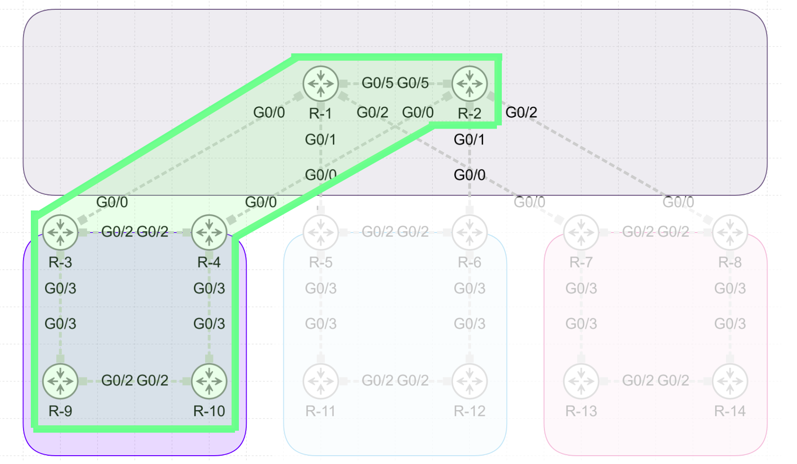
In this example I will focus on the top and left side of the topology.
Configuration L2 Routers (R1 & R2)
==== R1 & R2  (L2)

hostname R1
interface Loopback0
 ipv4 address 1.1.1.1 255.255.255.255
!
interface GigabitEthernet0/0/0/0
 ipv4 address 10.1.3.1 255.255.255.0
!
interface GigabitEthernet0/0/0/1
 ipv4 address 10.1.5.1 255.255.255.0
!
interface GigabitEthernet0/0/0/2
 ipv4 address 10.1.7.1 255.255.255.0

interface GigabitEthernet0/0/0/5
 ipv4 address 10.1.2.1 255.255.255.0
!
router isis 1
 is-type level-2-only
 net 49.000.0000.0000.0001.00
 address-family ipv4 unicast
  metric-style wide
 !
 interface Loopback0
  passive
  circuit-type level-2-only
  address-family ipv4 unicast
  !
 !
 interface GigabitEthernet0/0/0/0
  circuit-type level-2-only
  address-family ipv4 unicast
  !
 !
 interface GigabitEthernet0/0/0/1
  circuit-type level-2-only
  address-family ipv4 unicast
  !
 !
 interface GigabitEthernet0/0/0/2
  circuit-type level-2-only
  address-family ipv4 unicast
  !
 !
 interface GigabitEthernet0/0/0/5
  circuit-type level-2-only
  address-family ipv4 unicast
  !
 !
!
end
Configuration L1/L2 Routers (R3 & R4)
==== R3,R4,R5,R6,R7,R8  (L1/L2)

hostname R3
interface Loopback0
 ipv4 address 3.3.3.3 255.255.255.255
!
interface GigabitEthernet0/0/0/0
 DESC TO R1 UP (L2)
 ipv4 address 10.1.3.3 255.255.255.0
!
interface GigabitEthernet0/0/0/2
 DESC TO R4 RIGHT (L1/L2)
 ipv4 address 10.3.4.3 255.255.255.0
!
interface GigabitEthernet0/0/0/3
 DESC TO R9 DOWN (L1)
 ipv4 address 10.3.9.3 255.255.255.0
!
router isis 1
 net 49.001.0000.0000.0003.00
 address-family ipv4 unicast
  metric-style wide
 !
 interface Loopback0
  passive
  address-family ipv4 unicast
  !
 !
 interface GigabitEthernet0/0/0/0
  circuit-type level-2-only
  address-family ipv4 unicast
  !
 !
 interface GigabitEthernet0/0/0/2
  address-family ipv4 unicast
  !
 !
 interface GigabitEthernet0/0/0/3
  circuit-type level-1
  address-family ipv4 unicast
  !
 !
!
end
Configuration L1 Routers (R9 & R10)
==== R9,R10,R11,R12,R13,R14  (L1)

hostname R9

interface Loopback0
 ip address 9.9.9.9 255.255.255.255
 ip router isis 1
 isis circuit-type level-1
!
interface GigabitEthernet0/2
 ip address 10.9.10.9 255.255.255.0
 ip router isis 1
 isis circuit-type level-1
!
interface GigabitEthernet0/3
 ip address 10.3.9.9 255.255.255.0
 ip router isis 1
 isis circuit-type level-1
!
router isis 1
 net 49.0001.0000.0000.0009.00
 is-type level-1
 metric-style wide
!
Router Verifications
Verification L2 Routers (R1 & R2)
===== L2 Routers:

RP/0/0/CPU0:R1#sh isis interface brief
Thu Nov 21 10:54:53.132 UTC

IS-IS 1 Interfaces
    Interface      All     Adjs    Adj Topos  Adv Topos  CLNS   MTU    Prio
                   OK    L1   L2    Run/Cfg    Run/Cfg                L1   L2
-----------------  ---  ---------  ---------  ---------  ----  ----  --------
Lo0                Yes    -    -      0/0        1/1     No       -    -    -
Gi0/0/0/0          Yes    -    1*     1/1        1/1     Up    1497    -   64
Gi0/0/0/1          Yes    -    0      1/1        1/1     Up    1497    -   64
Gi0/0/0/2          Yes    -    0      1/1        1/1     Up    1497    -   64
Gi0/0/0/5          Yes    -    1*     1/1        1/1     Up    1497    -   64


RP/0/0/CPU0:R1#sh isis neighbors
Thu Nov 21 10:55:05.451 UTC

IS-IS 1 neighbors:
System Id      Interface        SNPA           State Holdtime Type IETF-NSF
R2             Gi0/0/0/5        5254.0006.6515 Up    25       L2   Capable
R3             Gi0/0/0/0        5254.0000.0d2a Up    28       L2   Capable

RP/0/0/CPU0:R1#sh isis protocol
Thu Nov 21 10:55:16.861 UTC

IS-IS Router: 1
  System Id: 0000.0000.0001
  Instance Id: 0
  IS Levels: level-2-only
  Manual area address(es):
    49.0000
  Routing for area address(es):
    49.0000
  Non-stop forwarding: Disabled
  Most recent startup mode: Cold Restart
  TE connection status: Down
  Topologies supported by IS-IS:
    IPv4 Unicast
      Level-2
        Metric style (generate/accept): Wide/Wide
        Metric: 10
        ISPF status: Disabled
      No protocols redistributed
      Distance: 115
      Advertise Passive Interface Prefixes Only: No
  SRLB allocated: 0 - 0
  SRGB not allocated
  Interfaces supported by IS-IS:
    Loopback0 is running passively (passive in configuration)
    GigabitEthernet0/0/0/0 is running actively (active in configuration)
    GigabitEthernet0/0/0/1 is running actively (active in configuration)
    GigabitEthernet0/0/0/2 is running actively (active in configuration)
    GigabitEthernet0/0/0/5 is running actively (active in configuration)


RP/0/0/CPU0:R1#sh ip route
Thu Nov 21 10:56:53.534 UTC

Codes: C - connected, S - static, R - RIP, B - BGP, (>) - Diversion path
       D - EIGRP, EX - EIGRP external, O - OSPF, IA - OSPF inter area
       N1 - OSPF NSSA external type 1, N2 - OSPF NSSA external type 2
       E1 - OSPF external type 1, E2 - OSPF external type 2, E - EGP
       i - ISIS, L1 - IS-IS level-1, L2 - IS-IS level-2
       ia - IS-IS inter area, su - IS-IS summary null, * - candidate default
       U - per-user static route, o - ODR, L - local, G  - DAGR, l - LISP
       A - access/subscriber, a - Application route
       M - mobile route, r - RPL, t - Traffic Engineering, (!) - FRR Backup path

Gateway of last resort is not set

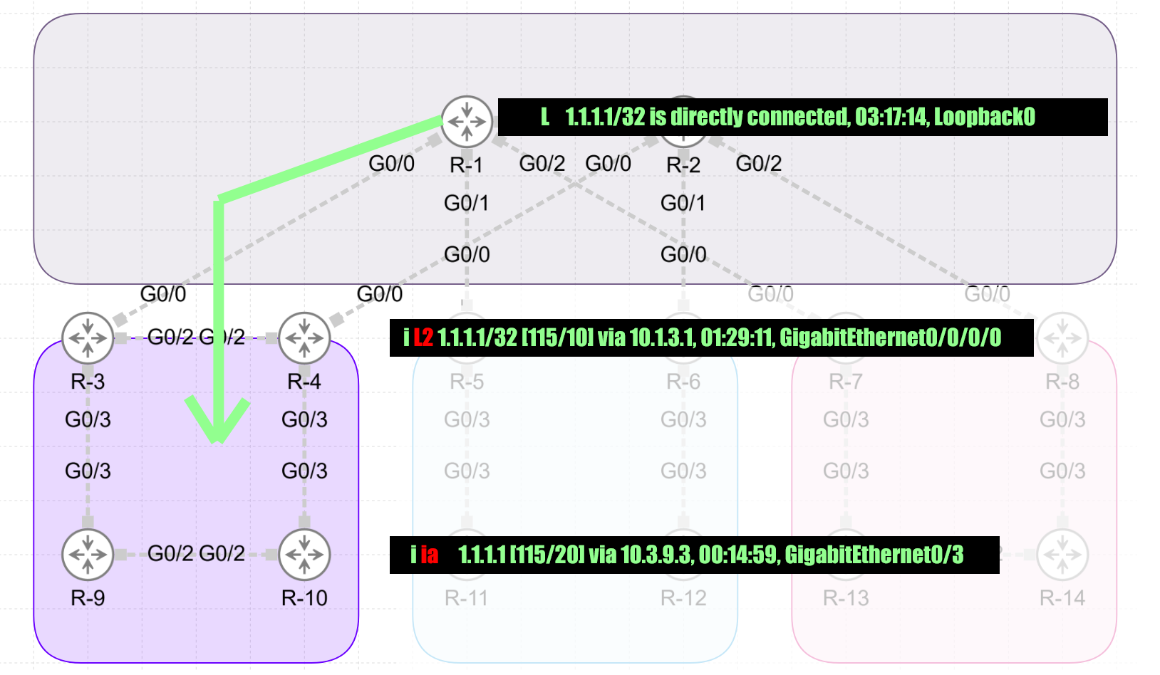
L    1.1.1.1/32 is directly connected, 03:17:14, Loopback0
i L2 2.2.2.2/32 [115/20] via 10.1.2.2, 02:42:46, GigabitEthernet0/0/0/5
i L2 3.3.3.3/32 [115/10] via 10.1.3.3, 01:22:09, GigabitEthernet0/0/0/0
i L2 4.4.4.4/32 [115/20] via 10.1.3.3, 01:14:31, GigabitEthernet0/0/0/0
i L2 9.9.9.9/32 [115/30] via 10.1.3.3, 01:14:31, GigabitEthernet0/0/0/0
C    10.1.2.0/24 is directly connected, 02:52:47, GigabitEthernet0/0/0/5
L    10.1.2.1/32 is directly connected, 02:52:47, GigabitEthernet0/0/0/5
C    10.1.3.0/24 is directly connected, 03:17:14, GigabitEthernet0/0/0/0
L    10.1.3.1/32 is directly connected, 03:17:14, GigabitEthernet0/0/0/0
i L2 10.1.4.0/24 [115/30] via 10.1.3.3, 01:14:31, GigabitEthernet0/0/0/0
C    10.1.5.0/24 is directly connected, 03:17:14, GigabitEthernet0/0/0/1
L    10.1.5.1/32 is directly connected, 03:17:14, GigabitEthernet0/0/0/1
C    10.1.7.0/24 is directly connected, 03:17:14, GigabitEthernet0/0/0/2
L    10.1.7.1/32 is directly connected, 03:17:14, GigabitEthernet0/0/0/2
i L2 10.2.4.0/24 [115/20] via 10.1.2.2, 02:42:46, GigabitEthernet0/0/0/5
i L2 10.2.6.0/24 [115/20] via 10.1.2.2, 02:42:46, GigabitEthernet0/0/0/5
i L2 10.2.8.0/24 [115/20] via 10.1.2.2, 02:42:46, GigabitEthernet0/0/0/5
i L2 10.3.4.0/24 [115/20] via 10.1.3.3, 01:22:09, GigabitEthernet0/0/0/0
i L2 10.3.9.0/24 [115/20] via 10.1.3.3, 01:22:09, GigabitEthernet0/0/0/0
i L2 10.4.10.0/24 [115/30] via 10.1.3.3, 01:14:31, GigabitEthernet0/0/0/0
i L2 10.9.10.0/24 [115/30] via 10.1.3.3, 01:22:09, GigabitEthernet0/0/0/0
i L2 10.10.10.10/32 [115/40] via 10.1.3.3, 00:00:28, GigabitEthernet0/0/0/0
Verification L1/L2 Routers (R3 & R4)
===== L1/L2 Routers:

RP/0/0/CPU0:R3#sh isis interface brief
Thu Nov 21 10:56:33.836 UTC

IS-IS 1 Interfaces
    Interface      All     Adjs    Adj Topos  Adv Topos  CLNS   MTU    Prio
                   OK    L1   L2    Run/Cfg    Run/Cfg                L1   L2
-----------------  ---  ---------  ---------  ---------  ----  ----  --------
Lo0                Yes    -    -      0/0        1/1     No       -    -    -
Gi0/0/0/0          Yes    -    1      1/1        1/1     Up    1497    -   64
Gi0/0/0/2          Yes    1*   1*     1/1        1/1     Up    1497   64   64
Gi0/0/0/3          Yes    1*   -      1/1        1/1     Up    1497   64    -


RP/0/0/CPU0:R3#sh isis neighbors
Thu Nov 21 10:56:02.668 UTC

IS-IS 1 neighbors:
System Id      Interface        SNPA           State Holdtime Type IETF-NSF
R4             Gi0/0/0/2        5254.0006.c602 Up    24       L1L2 Capable
R9             Gi0/0/0/3        5254.000b.6b54 Up    23       L1   Capable
R1             Gi0/0/0/0        5254.0016.8eeb Up    9        L2   Capable


RP/0/0/CPU0:R3#sh isis protocol
Thu Nov 21 10:58:38.648 UTC

IS-IS Router: 1
  System Id: 0000.0000.0003
  Instance Id: 0
  IS Levels: level-1-2
  Manual area address(es):
    49.0001
  Routing for area address(es):
    49.0001
  Non-stop forwarding: Disabled
  Most recent startup mode: Cold Restart
  TE connection status: Down
  Topologies supported by IS-IS:
    IPv4 Unicast
      Level-1
        Metric style (generate/accept): Wide/Wide
        Metric: 10
        ISPF status: Disabled
      Level-2
        Metric style (generate/accept): Wide/Wide
        Metric: 10
        ISPF status: Disabled
      No protocols redistributed
      Distance: 115
      Advertise Passive Interface Prefixes Only: No
  SRLB allocated: 0 - 0
  SRGB not allocated
  Interfaces supported by IS-IS:
    Loopback0 is running passively (passive in configuration)
    GigabitEthernet0/0/0/0 is running actively (active in configuration)
    GigabitEthernet0/0/0/2 is running actively (active in configuration)
    GigabitEthernet0/0/0/3 is running actively (active in configuration)


RP/0/0/CPU0:R3#sh ip route

Thu Nov 21 10:58:18.309 UTC
Codes: C - connected, S - static, R - RIP, B - BGP, (>) - Diversion path
       D - EIGRP, EX - EIGRP external, O - OSPF, IA - OSPF inter area
       N1 - OSPF NSSA external type 1, N2 - OSPF NSSA external type 2
       E1 - OSPF external type 1, E2 - OSPF external type 2, E - EGP
       i - ISIS, L1 - IS-IS level-1, L2 - IS-IS level-2
       ia - IS-IS inter area, su - IS-IS summary null, * - candidate default
       U - per-user static route, o - ODR, L - local, G  - DAGR, l - LISP
       A - access/subscriber, a - Application route
       M - mobile route, r - RPL, t - Traffic Engineering, (!) - FRR Backup path

Gateway of last resort is not set

i L2 1.1.1.1/32 [115/10] via 10.1.3.1, 01:22:38, GigabitEthernet0/0/0/0
i L2 2.2.2.2/32 [115/30] via 10.1.3.1, 01:22:38, GigabitEthernet0/0/0/0
L    3.3.3.3/32 is directly connected, 02:37:17, Loopback0
i L1 4.4.4.4/32 [115/10] via 10.3.4.4, 01:15:00, GigabitEthernet0/0/0/2
i L1 9.9.9.9/32 [115/20] via 10.3.9.9, 01:22:38, GigabitEthernet0/0/0/3
i L2 10.1.2.0/24 [115/20] via 10.1.3.1, 01:22:38, GigabitEthernet0/0/0/0
C    10.1.3.0/24 is directly connected, 02:37:17, GigabitEthernet0/0/0/0
L    10.1.3.3/32 is directly connected, 02:37:17, GigabitEthernet0/0/0/0
i L2 10.1.4.0/24 [115/20] via 10.3.4.4, 01:15:00, GigabitEthernet0/0/0/2
i L2 10.1.5.0/24 [115/20] via 10.1.3.1, 01:22:38, GigabitEthernet0/0/0/0
i L2 10.1.7.0/24 [115/20] via 10.1.3.1, 01:22:38, GigabitEthernet0/0/0/0
i L2 10.2.4.0/24 [115/30] via 10.1.3.1, 01:22:38, GigabitEthernet0/0/0/0
i L2 10.2.6.0/24 [115/30] via 10.1.3.1, 01:22:38, GigabitEthernet0/0/0/0
i L2 10.2.8.0/24 [115/30] via 10.1.3.1, 01:22:38, GigabitEthernet0/0/0/0
C    10.3.4.0/24 is directly connected, 02:37:17, GigabitEthernet0/0/0/2
L    10.3.4.3/32 is directly connected, 02:37:17, GigabitEthernet0/0/0/2
C    10.3.9.0/24 is directly connected, 02:37:17, GigabitEthernet0/0/0/3
L    10.3.9.3/32 is directly connected, 02:37:17, GigabitEthernet0/0/0/3
i L1 10.4.10.0/24 [115/20] via 10.3.4.4, 01:15:00, GigabitEthernet0/0/0/2
i L1 10.9.10.0/24 [115/20] via 10.3.9.9, 01:22:38, GigabitEthernet0/0/0/3
i L1 10.10.10.10/32 [115/30] via 10.3.4.4, 00:00:57, GigabitEthernet0/0/0/2
                    [115/30] via 10.3.9.9, 00:00:57, GigabitEthernet0/0/0/3
Verification L1 Routers (R9 & R10)
===== L1 Routers:

R10#show isis neighbors

Tag 1:
System Id       Type Interface     IP Address      State Holdtime Circuit Id
R6              L1   Gi0/3         10.6.10.6       UP    8        R6.05
R9              L1   Gi0/2         10.9.10.9       UP    23       R10.01
R10#
R10#show isis pro
R10#show isis protocol

Tag 1:
IS-IS Router: 1
  System Id: 0000.0000.0010.00  IS-Type: level-1
  Manual area address(es):
        49.0001
  Routing for area address(es):
        49.0001
  Interfaces supported by IS-IS:
        GigabitEthernet0/3 - IP
        GigabitEthernet0/2 - IP
        Loopback0 - IP
  Redistribute:
    static (on by default)
  Distance for L2 CLNS routes: 110
  RRR level: none
  Generate narrow metrics: none
  Accept narrow metrics:   none
  Generate wide metrics:   level-1-2
  Accept wide metrics:     level-1-2
IS-IS Levels Overview
IS-IS operates on a hierarchical two-level structure designed to enhance scalability and network organization. The two levels, Level 1 (L1) and Level 2 (L2), serve distinct roles.
Level 1 handles intra-area routing, where routers within the same area exchange topology information and compute routes only for that area. Level 1 routers are unaware of destinations outside their area and rely on Level 1/Level 2 (L1/L2) routers to forward traffic destined for other areas. This division simplifies the routing process within an area, reducing the size of the Link-State Database (LSDB) that each Level 1 router needs to maintain.
Level 2, on the other hand, serves as the backbone of the network and facilitates inter-area routing. Routers in Level 2 exchange topology information about all areas but do not have detailed knowledge of intra-area routes in Level 1.
L1/L2 routers act as bridges between these levels, connecting Level 1 areas to the Level 2 backbone. They advertise default routes into their respective Level 1 areas, allowing routers within those areas to reach external destinations via Level 2. This hierarchical structure improves scalability by containing routing information within levels while maintaining connectivity across the network.
- Level 1 (L1): Used for intra-area routing, where routers only exchange routing information with devices within the same area.
- Level 2 (L2): Used for inter-area routing, where routers act as the backbone, connecting different Level 1 areas.
Interlevel Routing Concepts
Interlevel routing in IS-IS is the mechanism that allows communication between Level 1 (intra-area) and Level 2 (inter-area) domains. At its core, it relies on L1/L2 routers, which serve as gateways connecting Level 1 areas to the Level 2 backbone. These routers facilitate traffic flow from Level 1 routers to destinations outside their area by advertising a default route into the Level 1 area. This default route simplifies the routing tables of Level 1 routers by directing any unknown destination traffic to the nearest L1/L2 router, which then forwards it through the Level 2 backbone to its destination.
Another critical aspect of interlevel routing is route leaking, which provides finer control over the information shared between levels. By default, IS-IS does not advertise Level 1 routes into Level 2 or vice versa to maintain scalability and avoid unnecessary routing table growth. However, in certain scenarios, specific Level 1 routes can be selectively “leaked” into Level 2 to optimize traffic flows or reduce reliance on default routing. Similarly, key Level 2 routes can be advertised into Level 1 to improve local reachability. These interlevel routing concepts enable IS-IS to maintain a scalable and efficient hierarchy while offering flexibility for advanced routing policies.
-
L1/L2 Routers:
- Act as a bridge between Level 1 and Level 2.
- Advertise default routes from Level 2 into Level 1 areas, enabling L1 routers to reach destinations outside their area.
-
Route Leaking:
- By default, L2 routes are not advertised into L1.
- Route leaking enables specific prefixes from Level 2 to be advertised into Level 1.
- Useful for reducing dependency on default routing or optimizing traffic flows.
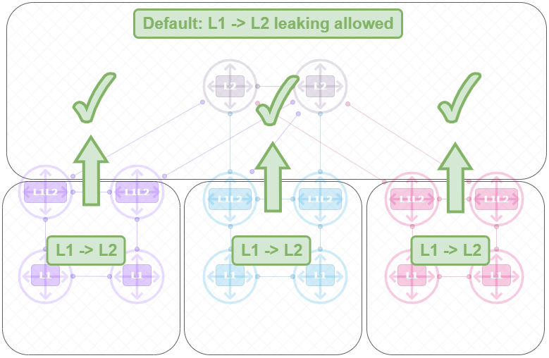
Default Routeleaking behavior visualized
Default L1 -> L2 Leaking Allowed;
Default L2 -> L1 Leaking Blocked;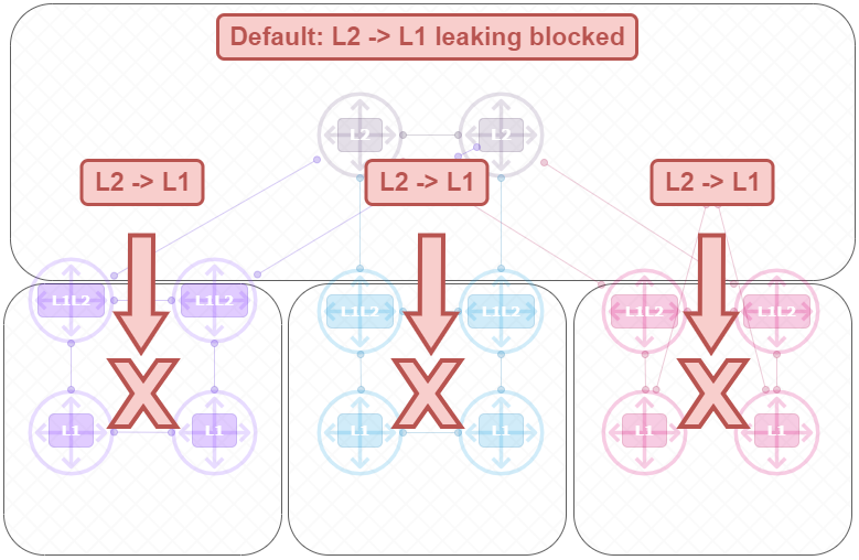
IS-IS Level2 into Level1 – Route leaking configuration
In this example I will focus on the top and left side of the topology. Here I will route leake the Loopback of Router1 (1.1.1.1/32 , Level2 route) into area1 (Level1, bottom left). While the L1/L2 Routers already provide routing between levels with a default route, this will also advertise the L2 route in the L1 area.
Configuration L1/L2 Routers (R3 & R4)
==== R3 & R4

prefix-set PREFIX-LIST                                            ==== Prefix-set with the loopback of R1
  1.1.1.1/32
end-set
!

route-policy LEAK-LVL2-LVL1                                       ==== Route-policy
  if destination in PREFIX-LIST then
    pass
  endif
end-policy
!

router isis 1
 net 49.001.0000.0000.0003.00
 address-family ipv4 unicast
  metric-style wide
  propagate level 2 into level 1 route-policy LEAK-LVL2-LVL1     ==== Propagate L2 into L2
 !
 interface Loopback0
  passive
  address-family ipv4 unicast
  !
 !
Verification on L1 Routers (R9 & R10)
=========== BEFORE ROUTE-LEAK

R9#sh ip route
--
Gateway of last resort is 10.3.9.3 to network 0.0.0.0

i*L1  0.0.0.0/0 [115/10] via 10.3.9.3, 01:08:56, GigabitEthernet0/3
      3.0.0.0/32 is subnetted, 1 subnets
i L1     3.3.3.3 [115/10] via 10.3.9.3, 01:08:56, GigabitEthernet0/3
      4.0.0.0/32 is subnetted, 1 subnets
i L1     4.4.4.4 [115/20] via 10.3.9.3, 01:01:21, GigabitEthernet0/3
      9.0.0.0/32 is subnetted, 1 subnets
C        9.9.9.9 is directly connected, Loopback0
      10.0.0.0/8 is variably subnetted, 6 subnets, 2 masks
i L1     10.3.4.0/24 [115/20] via 10.3.9.3, 01:08:56, GigabitEthernet0/3
C        10.3.9.0/24 is directly connected, GigabitEthernet0/3
L        10.3.9.9/32 is directly connected, GigabitEthernet0/3
i L1     10.4.10.0/24 [115/30] via 10.3.9.3, 01:01:21, GigabitEthernet0/3
C        10.9.10.0/24 is directly connected, GigabitEthernet0/2
L        10.9.10.9/32 is directly connected, GigabitEthernet0/2
i L1     10.10.10.10/32 [115/20] via 10.9.10.10, 00:03:32, GigabitEthernet0/2


=========== AFTER ROUTE-LEAK

R9#sh ip route
----
Gateway of last resort is 10.3.9.3 to network 0.0.0.0

i*L1  0.0.0.0/0 [115/10] via 10.3.9.3, 01:24:54, GigabitEthernet0/3
      1.0.0.0/32 is subnetted, 1 subnets
i ia     1.1.1.1 [115/20] via 10.3.9.3, 00:14:59, GigabitEthernet0/3     ===== R1 L0 ( ia - IS-IS inter area )
      3.0.0.0/32 is subnetted, 1 subnets
i L1     3.3.3.3 [115/10] via 10.3.9.3, 01:24:54, GigabitEthernet0/3
      4.0.0.0/32 is subnetted, 1 subnets
i L1     4.4.4.4 [115/20] via 10.9.10.10, 00:03:32, GigabitEthernet0/2
                 [115/20] via 10.3.9.3, 00:03:32, GigabitEthernet0/3
      9.0.0.0/32 is subnetted, 1 subnets
C        9.9.9.9 is directly connected, Loopback0
      10.0.0.0/8 is variably subnetted, 7 subnets, 2 masks
i L1     10.3.4.0/24 [115/20] via 10.3.9.3, 01:24:54, GigabitEthernet0/3
C        10.3.9.0/24 is directly connected, GigabitEthernet0/3
L        10.3.9.9/32 is directly connected, GigabitEthernet0/3
i L1     10.4.10.0/24 [115/20] via 10.9.10.10, 00:03:32, GigabitEthernet0/2
C        10.9.10.0/24 is directly connected, GigabitEthernet0/2
L        10.9.10.9/32 is directly connected, GigabitEthernet0/2
i L1     10.10.10.10/32 [115/20] via 10.9.10.10, 00:03:32, GigabitEthernet0/2
Summary
By default, L1 routers in IS-IS rely on a default route from L1/L2 routers for external connectivity. L2 routes are not advertised into L1 areas unless explicitly configured via route leaking. This design minimizes routing table size and computational overhead in L1 areas, improving scalability.
