MPLS – Fast Reroute (FRR) and TI-LFA
What is Fast Reroute (FRR) in an MPLS network?
In an MPLS network with Segment Routing (SR), ensuring rapid recovery from link or node failures is crucial for maintaining high network availability. Cisco’s IOS-XR supports various Fast Reroute (FRR) mechanisms within MPLS Segment Routing environments, including Link Protection, Node Protection, and Topology Independent Loop-Free Alternate (TI-LFA). This article will provide a configuration guide and explanations for these MPLS-SR FRR mechanisms in an MPLS SR-enabled network running OSPF as the Interior Gateway Protocol (IGP).
What is TI-LFA in an MPLS network?
TI-LFA (Topology-Independent Loop-Free Alternate) is a fast reroute (FRR) mechanism in MPLS Segment Routing (MPLS-SR) designed to provide sub-50ms recovery from link or node failures in IP/MPLS networks. Unlike traditional LFA, which relies on specific topological conditions and may not cover all failure scenarios, TI-LFA is “topology-independent,” meaning it ensures protection for all traffic flows regardless of network topology. TI-LFA works by precomputing backup paths based on Segment Routing (SR) policies, allowing traffic to be quickly rerouted through alternate paths without complex recalculations. In the event of a failure, traffic is redirected via pre-established repair paths that adhere to the shortest path routing principles (SPF), minimizing packet loss and maintaining high availability across the network.
MPLS-SR Lab Setup (Baseline)
Labs download |
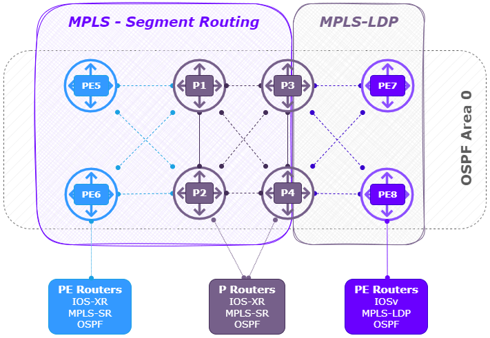
Using Cisco’s Modeling Labs (CML) I build the following MPLS-SR lab using OSPF as the IGP.
- 2 x PE router ( Left ) (PE5, PE6) running XRv with IOS-XR.
- 4 x P router ( Center ) (P1, P2, P3, P4) running XRv with IOS-XR.
- 2 x PE router ( Right ) (PE7, PE8) running IOSv with IOS.
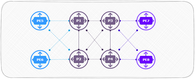
Logical View:
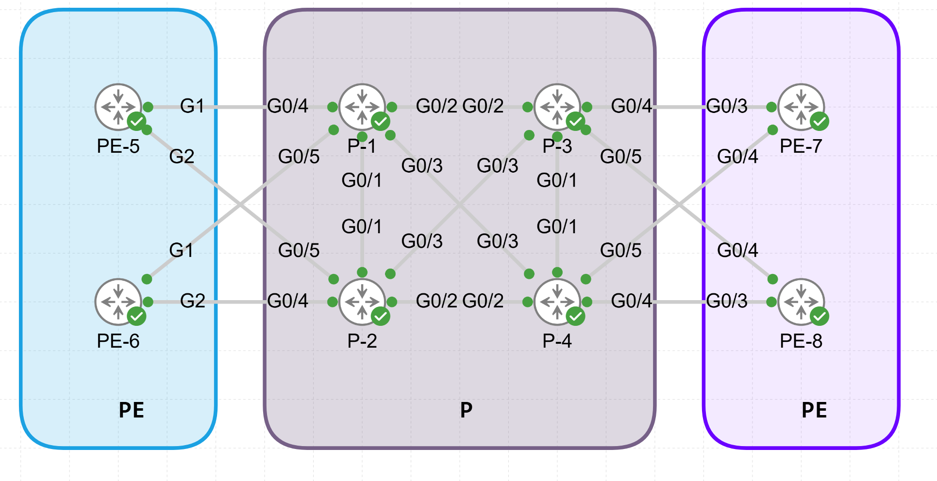
Interfaces:
IP Addressing:
The point-to-point links are configured with the following IP addressing scheme:
- “10.<Lowest Router Id>.<Highest Router Id>.<Router Id>./24.”
For example the link between P1 and P2 gives on P1: 10.1.2.1/24 and on P2: 10.1.2.2/24.
| Device | Function | Loopback address | Subnets | Label Ranges | Image |
|---|---|---|---|---|---|
| P1 | P Router | 1.1.1.1/32 | Gi1 10.1.2.1/24 Gi2 10.1.3.1/24 Gi3 10.1.4.1/24 Gi4 10.1.5.1/24 Gi5 10.1.6.1/24 | 24100-24199 | IOS XRV |
| P2 | P Router | 2.2.2.2/32 | Gi1 10.1.2.2/24 Gi2 10.2.4.2/24 Gi3 10.2.3.2/24 Gi4 10.2.6.2/24 Gi5 10.2.5.2/24 | 24200-24299 | IOS XRV |
| P3 | P Router | 3.3.3.3/32 | Gi1 10.3.4.3/24 Gi2 10.1.3.3/24 Gi3 10.2.3.3/24 Gi4 10.3.7.3/24 Gi5 10.3.8.3/24 | 24300-24399 | IOS XRV |
| P4 | PE Router | 4.4.4.4/32 | Gi1 10.3.4.4/24 Gi2 10.2.4.4/24 Gi3 10.1.4.4/24 Gi4 10.4.8.4/24 Gi5 10.4.7.4/24 | 24400-24499 | IOS XRV |
| PE5 | PE Router | 5.5.5.5/32 | Gi1 10.1.5.5/24 Gi2 10.2.5.5/24 | 24500-24599 | IOS XRV |
| PE6 | PE Router | 6.6.6.6/32 | Gi1 10.1.6.6/24 Gi2 10.2.6.6/24 | 24600-246909 | IOS XRV |
| PE7 | PE Router | 7.7.7.7/32 | GE0/3 10.3.7.7/24 GE0/4 10.4.7.7/24 | 700-799 | IOSv |
| PE8 | PE Router | 8.8.8.8/32 | GE0/3 10.4.8.8/24 GE0/4 10.3.8.8/24 | 800-899 | IOSv |
Verification on Router P1:
RP/0/0/CPU0:P-1#show ospf database
Wed Nov 13 14:00:31.151 UTC


            OSPF Router with ID (1.1.1.1) (Process ID 1)

                Router Link States (Area 0)

Link ID         ADV Router      Age         Seq#       Checksum Link count
1.1.1.1         1.1.1.1         363         0x80000011 0x00ceba 11
2.2.2.2         2.2.2.2         363         0x80000011 0x00670d 11
3.3.3.3         3.3.3.3         1367        0x8000000f 0x00cbc4 10
4.4.4.4         4.4.4.4         1343        0x80000010 0x009999 11
5.5.5.5         5.5.5.5         738         0x8000000e 0x005cf3 5
6.6.6.6         6.6.6.6         972         0x8000000e 0x00231b 5
7.7.7.7         7.7.7.7         1297        0x80000005 0x00f2fe 6
8.8.8.8         8.8.8.8         1323        0x80000003 0x00a5c5 3


RP/0/0/CPU0:P-1#show mpls interfaces
Wed Nov 13 14:00:40.501 UTC
Interface                  LDP      Tunnel   Static   Enabled
-------------------------- -------- -------- -------- --------
GigabitEthernet0/0/0/1     No       No       No       Yes
GigabitEthernet0/0/0/2     No       No       No       Yes
GigabitEthernet0/0/0/3     No       No       No       Yes
GigabitEthernet0/0/0/4     No       No       No       Yes
GigabitEthernet0/0/0/5     No       No       No       Yes


RP/0/0/CPU0:P-1#show mpls ldp neighbor brief
Sun Nov  3 19:07:44.450 UTC

Peer               GR  NSR  Up Time     Discovery   Addresses     Labels
                                        ipv4  ipv6  ipv4  ipv6  ipv4   ipv6
-----------------  --  ---  ----------  ----------  ----------  ------------
5.5.5.5:0          N   N    01:43:44    1     0     3     0     22     0
6.6.6.6:0          N   N    01:43:43    1     0     3     0     22     0
2.2.2.2:0          N   N    01:43:28    1     0     6     0     22     0
4.4.4.4:0          N   N    01:41:52    1     0     6     0     22     0
3.3.3.3:0          N   N    01:40:00    1     0     6     0     22     0

RP/0/0/CPU0:P-1#show mpls forwarding
Wed Nov 13 14:01:25.328 UTC
Local  Outgoing    Prefix             Outgoing     Next Hop        Bytes
Label  Label       or ID              Interface                    Switched
------ ----------- ------------------ ------------ --------------- ------------
16002  Pop         SR Pfx (idx 2)     Gi0/0/0/1    10.1.2.2        0
16003  Pop         SR Pfx (idx 3)     Gi0/0/0/2    10.1.3.3        0
16004  Pop         SR Pfx (idx 4)     Gi0/0/0/3    10.1.4.4        0
16005  Pop         SR Pfx (idx 5)     Gi0/0/0/4    10.1.5.5        0
16006  Pop         SR Pfx (idx 6)     Gi0/0/0/5    10.1.6.6        0
16007  16007       SR Pfx (idx 7)     Gi0/0/0/2    10.1.3.3        0
       16007       SR Pfx (idx 7)     Gi0/0/0/3    10.1.4.4        0
16008  16008       SR Pfx (idx 8)     Gi0/0/0/3    10.1.4.4        0
24100  Pop         SR Adj (idx 0)     Gi0/0/0/1    10.1.2.2        0
24101  Pop         SR Adj (idx 0)     Gi0/0/0/5    10.1.6.6        0
24102  Pop         SR Adj (idx 0)     Gi0/0/0/4    10.1.5.5        0
24103  Pop         SR Adj (idx 0)     Gi0/0/0/2    10.1.3.3        0
24104  Pop         SR Adj (idx 0)     Gi0/0/0/3    10.1.4.4        0
Router Configurations
The baseline topology is configured with MPLS, Segment Routing, and all routers in OSPF area 0.
IOX-XR Routers (P1, P2, P3, P4, PE5, PE6)
The IOS-XR Routers are configured with the standard subnetting scheme from the table above in combination with OSPF area 0 and Segment Routing as the labelling protocol. The Label range is based on the Router number. I start the label ranges after the MPLS-SR SRGB Block (16000-23999) at 24000 and up. For these routers I use the the lightweight IOS-XR (XRv) image which supports MPLS-SR.
(P1, P2, P3, P4)
#change the values where needed.


# ============= Interfaces
interface Loopback0
 ipv4 address 1.1.1.1 255.255.255.255
!
interface GigabitEthernet0/0/0/0
 shutdown
!
interface GigabitEthernet0/0/0/1
 ipv4 address 10.1.2.1 255.255.255.0
!
interface GigabitEthernet0/0/0/2
 ipv4 address 10.1.3.1 255.255.255.0
!
interface GigabitEthernet0/0/0/3
 ipv4 address 10.1.4.1 255.255.255.0
!
interface GigabitEthernet0/0/0/4
 ipv4 address 10.1.5.1 255.255.255.0
!
interface GigabitEthernet0/0/0/5
 ipv4 address 10.1.6.1 255.255.255.0

# ============= MPLS
# ============= MPLS Label range = 24000 + Router ID
mpls label range table 0 24100 24199
!
segment-routing
 mapping-server
  prefix-sid-map
   address-family ipv4
    7.7.7.7/32 7 range 1
    8.8.8.8/32 8 range 1
   !
  !
 !
!

# ============= OSPF
router ospf 1
 segment-routing mpls
 segment-routing forwarding mpls
 segment-routing sr-prefer
 segment-routing prefix-sid-map advertise-local
 address-family ipv4
 area 0
  interface Loopback0
   prefix-sid index 1
  !
  interface GigabitEthernet0/0/0/0
   network point-to-point
  !
  interface GigabitEthernet0/0/0/1
   network point-to-point
  !
  interface GigabitEthernet0/0/0/2
   network point-to-point
  !
  interface GigabitEthernet0/0/0/3
   network point-to-point
  !
  interface GigabitEthernet0/0/0/4
   network point-to-point
  !
  interface GigabitEthernet0/0/0/5
   network point-to-point
  !
 !
MPLS – Fast Reroute with Link Protection
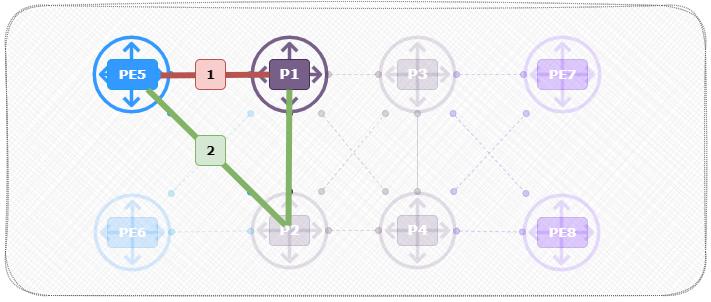
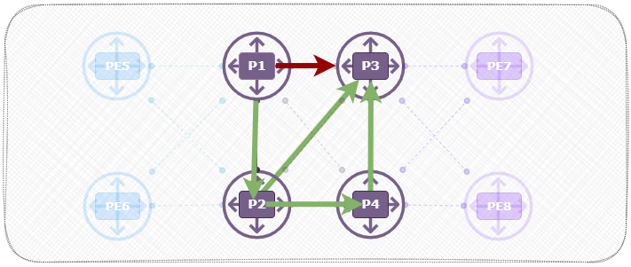
Link Protection aims to protect traffic against individual link failures by creating a backup path around the failed link. When a link fails, the traffic is directed over a backup path to the next-hop router. This redirection is rapid, as it does not depend on global re-convergence of the routing protocol.
In this example I will look at link protection between PE5 and P1. The default behavior is via Path1 to the next-hop P1. After enabling fast-reroute I will configure a backup path via Path2.
With link protection enabled, the router will dynamically compute a backup path in the event of a link failure. This is particularly useful in networks where link reliability is a primary concern.
MPLS – Fast Reroute with Node Protection
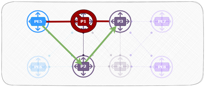
Node Protection provides protection against router failures, not just link failures. In this scenario, traffic will be redirected around the entire failed node rather than just a single link.
In this example I will look at the scenario where P1 fails. The default behavior is via Path1 to the next-hop P1. After enabling fast-reroute with node protection it will configure a backup path via Path2.
In case the neighboring router fails, the traffic will be redirected along a path that circumvents both the failed router and its connected links, ensuring continuity of data flow without waiting for IGP convergence.
MPLS-SR – Fast Reroute Per-Link vs Per-Prefix
The key difference between fast-reroute per-link and fast-reroute per-prefix lies in the level at which backup paths are created for MPLS Fast Reroute (FRR) protection:
-
fast-reroute per-link(also known as link-based protection) creates a single backup path for each link. This means that all traffic routed through a particular link will share the same backup path if that link fails. This approach is simpler and consumes fewer resources, as only one alternate path is needed per link, but it may not always be optimal for individual prefixes or specific destinations. It works well in networks where traffic can be uniformly redirected. -
fast-reroute per-prefix(also known as per-prefix protection) creates individual backup paths for each prefix (destination) that could be affected by a failure. This allows for more granular, optimized failover paths that are specific to each destination, which can lead to better traffic distribution and higher performance, especially in complex topologies. However, it can consume more resources because it requires maintaining multiple backup paths for different prefixes or destinations.
router ospf 1
 segment-routing mpls
 segment-routing forwarding mpls
 fast-reroute per-link
 segment-routing sr-prefer
!


==== Before FFR

RP/0/0/CPU0:PE-5#sh route 1.1.1.1/32
Wed Nov 13 14:21:13.126 UTC

Routing entry for 1.1.1.1/32
  Known via "ospf 1", distance 110, metric 2, labeled SR, type intra area
  Installed Nov 13 14:21:10.577 for 00:00:02
  Routing Descriptor Blocks
    10.1.5.1, from 1.1.1.1, via GigabitEthernet0/0/0/1
      Route metric is 2
  No advertising protos.

==== After FFR

RP/0/0/CPU0:PE-5#sh route 1.1.1.1/32
Wed Nov 13 14:22:15.782 UTC

Routing entry for 1.1.1.1/32
  Known via "ospf 1", distance 110, metric 2, labeled SR, type intra area
  Installed Nov 13 14:22:13.682 for 00:00:02
  Routing Descriptor Blocks
    10.1.5.1, from 1.1.1.1, via GigabitEthernet0/0/0/1, Protected
      Route metric is 2
    10.2.5.2, from 1.1.1.1, via GigabitEthernet0/0/0/2, Backup (Local-LFA)
      Route metric is 0
  No advertising protos.
MPLS-SR – Fast Reroute with Topology Independent Loop-Free Alternate (TI-LFA)
Topology Independent Loop-Free Alternate (TI-LFA) is an advanced FRR mechanism that provides sub-50ms failover in MPLS-SR networks. Unlike standard LFA, TI-LFA can handle more complex topologies and guarantee fast reroute even in environments where link and node protection mechanisms might fall short.
TI-LFA is particularly valuable in complex or meshed topologies where standard LFA might not provide a viable backup path. By leveraging Segment Routing, TI-LFA can create backup paths that avoid not only immediate failures but also potential loop scenarios.
RP/0/0/CPU0:PE-5(config-ospf)#fast-reroute per-prefix ?
  exclude             Per-prefix LFA exclusion information
  lfa-candidate       FRR LFA candidate information
  load-sharing        Load share prefixes across multiple backups
  priority-limit      Limit backup computation upto the prefix priority
  remote-lfa          Remote LFA computation
  ti-lfa              Topology Independent LFA computation
  tiebreaker          Configure tiebreaker for multiple backups
  use-candidate-only  Enable/Disable backup selection from candidate-list only
  <cr>


router ospf 1
 segment-routing mpls
 segment-routing forwarding mpls
 fast-reroute per-prefix
 fast-reroute per-prefix ti-lfa enable
MPLS-SR – Topology Independent Loop-Free Alternate (TI-LFA) tie-breakers
Topology Independent Loop-Free Alternate (TI-LFA) tie-breakers are mechanisms used to select the optimal backup path when there are multiple viable backup options available in a network. In the context of TI-LFA, which is a Fast Reroute (FRR) technique, these tie-breakers help determine the best failover path that satisfies Segment Routing (SR) requirements, particularly when providing fast and loop-free recovery in the event of a link or node failure.
Purpose of TI-LFA Tie-Breakers
When multiple backup paths qualify as loop-free alternates (LFAs), the router needs to decide which path to use. Tie-breakers provide criteria for choosing the “best” backup path based on factors such as shortest path, least-cost, or other customized rules. TI-LFA uses the SR concept of “repair paths” that avoid the failure and can be achieved using Segment Routing paths.
The selection process for TI-LFA backup paths typically involves several tie-breakers in a specific order. Cisco IOS-XR provides flexibility to modify this order to best fit network design requirements. Here are common tie-breakers in TI-LFA and what they aim to achieve:
Minimize SID Stack Depth:
This tie-breaker prefers paths that use the fewest number of Segment Identifiers (SIDs). A smaller SID stack generally translates to reduced overhead on the router since fewer segments need to be pushed onto the packet. This minimizes complexity and can improve forwarding performance.
Minimize Path Cost:
This tie-breaker selects paths based on the lowest IGP cost. This means the router will choose the backup path with the shortest IGP metric, ensuring that the path is as direct as possible, which can help reduce latency.
Prefer Node Protection:
If both link protection and node protection are available, this tie-breaker gives preference to node protection paths. Node protection ensures that the backup path bypasses not only the failed link but also the next-hop router, providing more robust protection against failures.
Minimize Label Stack Depth:
In MPLS-based SR environments, label stack depth refers to the number of MPLS labels in the backup path. This tie-breaker selects paths with the smallest label stack, minimizing processing requirements and simplifying packet handling.
Minimize Backup Path Delay:
This tie-breaker selects paths based on the lowest delay metric. By choosing paths with minimal delay, the router can ensure that traffic is redirected as quickly as possible, providing a seamless transition for delay-sensitive applications.
User-Defined or Custom Tie-Breakers:
Some routers, including Cisco IOS-XR, allow for custom tie-breaking rules that network administrators can configure. This customization can take into account specific business requirements or traffic engineering needs.
Default Tie-Breaker Order in Cisco IOS-XR
Cisco IOS-XR follows a default order of TI-LFA tie-breakers, but network administrators can adjust this order based on network priorities. The default order generally prioritizes Minimize SID Stack Depth first, followed by Minimize Path Cost and Prefer Node Protection. This order strikes a balance between simplicity (low SID stack) and robustness (node protection).
MPLS-SR FRR Verification
After configuring the above protections, you can verify the FRR settings using the following IOS-XR commands:
RP/0/0/CPU0:PE-5#show ospf fast-reroute topology 1.1.1.1

            OSPF Router with ID (5.5.5.5) (Process ID 1)

  IPFRR Topology for Node 1.1.1.1, Area 0 , LFA revision 25

  Node-ID               Distance      Type        Revision    rSPT-distance   rSPT-poison
  1.1.1.1               0             1           25          0               N
  2.2.2.2               1             1           25          1               N
  3.3.3.3               1             1           25          1               N
  4.4.4.4               1             1           25          1               N
  5.5.5.5               1             1           25          1               Y
  6.6.6.6               1             1           25          1               N
  7.7.7.7               2             1           25          2               N
  8.8.8.8               2             1           25          2               N


==== Prefix two hops away:

RP/0/0/CPU0:PE-5#show route 3.3.3.3/32

Routing entry for 3.3.3.3/32
  Known via "ospf 1", distance 110, metric 3, labeled SR, type intra area
  Installed Nov 13 14:22:13.682 for 19:27:36
  Routing Descriptor Blocks
    10.1.5.1, from 3.3.3.3, via GigabitEthernet0/0/0/1, Protected, Backup (Local-LFA)
      Route metric is 3
    10.2.5.2, from 3.3.3.3, via GigabitEthernet0/0/0/2, Protected, Backup (Local-LFA)
      Route metric is 3
  No advertising protos.

==== Prefix one hops away:

RP/0/0/CPU0:PE-5#show route 2.2.2.2/32

Routing entry for 2.2.2.2/32
  Known via "ospf 1", distance 110, metric 2, labeled SR, type intra area
  Installed Nov 13 14:22:13.682 for 19:27:41
  Routing Descriptor Blocks
    10.1.5.1, from 2.2.2.2, via GigabitEthernet0/0/0/1, Backup (Local-LFA)
      Route metric is 0
    10.2.5.2, from 2.2.2.2, via GigabitEthernet0/0/0/2, Protected
      Route metric is 2
  No advertising protos.

=============== OSPF backup-paths

---- omitted for brevity ----
RP/0/0/CPU0:PE-5#show ospf route backup-path detail

OSPF Route entry for 3.3.3.3/32
  Route type:  Intra-area
  Last updated: Nov 13 07:46:30.699
  Metric: 3
    SPF priority: 4,  SPF version: 27
  RIB version: 0,  Source: Unknown
       10.1.5.1, from 3.3.3.3, via GigabitEthernet0/0/0/1, path-id 2
           Backup path:
              10.2.5.2, from 3.3.3.3, via GigabitEthernet0/0/0/2, protected bitmap 0000000000000002
              Attributes: Metric: 3, Primary, Downstream, Node Protect, SRLG Disjoint
       10.2.5.2, from 3.3.3.3, via GigabitEthernet0/0/0/2, path-id 1
           Backup path:
              10.1.5.1, from 3.3.3.3, via GigabitEthernet0/0/0/1, protected bitmap 0000000000000001
              Attributes: Metric: 3, Primary, Downstream, Node Protect, SRLG Disjoint
---- omitted for brevity ----

=============== cef details

RP/0/0/CPU0:PE-5#sh cef 3.3.3.3/32 detail

3.3.3.3/32, version 240, labeled SR, internal 0x1000001 0x83 (ptr 0xa136decc) [1], 0x0 (0xa1353614), 0xa28 (0xa16f412c)
 Updated Nov 13 14:22:13.702
 local adjacency 10.1.5.1
 Prefix Len 32, traffic index 0, precedence n/a, priority 1
 Extensions: context-label:16003
  gateway array (0xa12b804c) reference count 15, flags 0x400068, source rib (7), 0 backups
                [6 type 5 flags 0x8401 (0xa15415b4) ext 0x0 (0x0)]
  LW-LDI[type=5, refc=3, ptr=0xa1353614, sh-ldi=0xa15415b4]
  gateway array update type-time 1 Nov 13 14:22:13.702
 LDI Update time Nov 13 14:22:13.702
 LW-LDI-TS Nov 13 14:22:13.702
   via 10.1.5.1/32, GigabitEthernet0/0/0/1, 8 dependencies, weight 0, class 0, protected, backup (Local-LFA) [flags 0x600]
    path-idx 0 bkup-idx 1 NHID 0x0 [0xa17aa0e4 0x0]
    next hop 10.1.5.1/32
     local label 16003      labels imposed {16003}
   via 10.2.5.2/32, GigabitEthernet0/0/0/2, 8 dependencies, weight 0, class 0, protected, backup (Local-LFA) [flags 0x600]
    path-idx 1 bkup-idx 0 NHID 0x0 [0xa17aa314 0x0]
    next hop 10.2.5.2/32
     local label 16003      labels imposed {16003}


    Load distribution: 0 1 (refcount 6)

    Hash  OK  Interface                 Address
    0     Y   GigabitEthernet0/0/0/1    10.1.5.1
    1     Y   GigabitEthernet0/0/0/2    10.2.5.2
MPLS FRR Summary
By configuring these Fast ReRoute options in MPLS Segment Routing, you can ensure high availability and resilience within your network. Here’s a quick recap:
- Link Protection: Redirects traffic around failed links, suitable for scenarios with isolated link failures.
- Node Protection: Provides a backup path around failed routers, ensuring resilience against router outages.
- TI-LFA: Uses segment routing to calculate backup paths independent of topology, ideal for complex networks needing rapid failover.
Properly implementing FRR in MPLS-SR with OSPF enables rapid network recovery, enhancing the reliability and performance of your MPLS network. Each method provides unique protection suited to specific network requirements, ensuring minimal disruption to data flows in the event of failures.

