IS-IS Redistribution and Route Summarization

Intermediate System to Intermediate System (IS-IS)
Intermediate System to Intermediate System (IS-IS) is a dynamic link-state routing protocol widely used in large-scale networks, especially in service provider environments. In this post I will look at the following IS-IS configurations;
- Redistribution of OSPF into IS-IS, and the differences between L1 and L2.
- IS-IS Path selection when L1 and L2 routes are available.
- How and where to apply IS-IS Route Summarization.
IS-IS Lab Setup
Labs download |
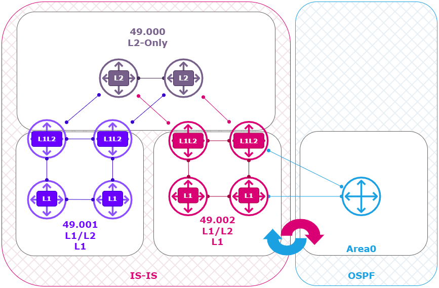
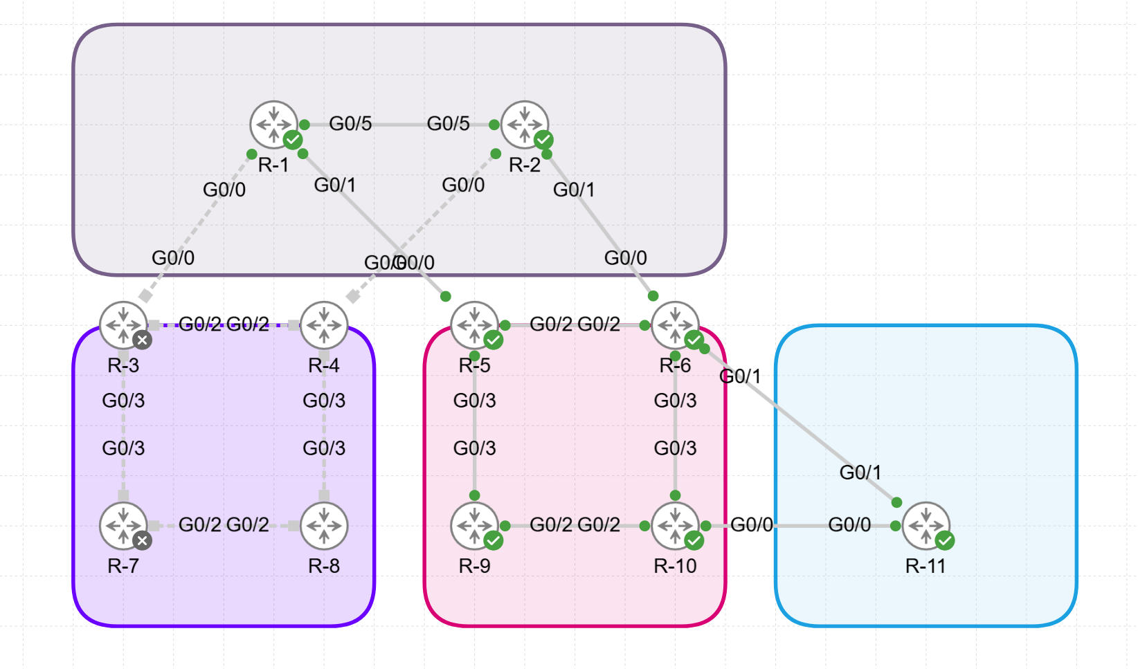
Using Cisco’s Modeling Labs (CML) I build the following IS-IS and OSPF topology:
- 2 x L2 Router ( Top ) (R1, R2) running XRv with IOS-XR.
- 2 x L1L2 Router ( left ) (R3, R4) running XRv with IOS-XR.
- 2 x L1 Router ( left ) (R7, R8) running IOS with IOSv.
- 2 x L1L2 Router ( Center ) (R5, R6) running XRv with IOS-XR.
- 2 x L1 Router ( Center ) (R9, R10) running IOS with IOSv.
- 1 x OSPF Router (R11) running IOS with IOSv.
Logical View:
Physical View:
IP Addressing:
The point-to-point links are configured with the following IP addressing scheme:
- “10.<Lowest Router Id>.<Highest Router Id>.<Router Id>./24.”
For example the link between R1 and R 2 gives on P1: 10.1.2.1/24 and on P2: 10.1.2.2/24.
| Device | Function | Loopback address | Subnets | Image |
|---|---|---|---|---|
| R1 | L2 Router (Backbone) | 1.1.1.1/32 | G0 10.1.3.1/24 G1 10.1.5.1/24 G5 10.1.2.1/24 | IOS XRV |
| R2 | L2 Router (Backbone) | 2.2.2.2/32 | G0 10.2.4.2/24 G1 10.2.6.2/24 G5 10.1.2.2/24 | IOS XRV |
| R3 | L1/L2 Router | 3.3.3.3/32 | G0 10.1.3.3/24 G2 10.3.4.3/24 G3 10.3.7.3/24 | IOS XRV |
| R4 | L1/L2 Router | 4.4.4.4/32 | G0 10.2.4.4/24 G2 10.3.4.4/24 G3 10.3.8.4/24 | IOS XRV |
| R5 | L1/L2 Router | 5.5.5.5/32 | G0 10.1.5.5/24 G2 10.5.6.5/24 G3 10.5.9.5/24 | IOS XRV |
| R6 | L1/L2 Router | 6.6.6.6/32 | G0 10.2.6.6/24 G1 10.6.11.6/24 G2 10.5.6.6/24 G3 10.6.10.6/24 | IOS XRV |
| R7 | L1 Router | 7.7.7.7/32 | G2 10.7.8.7/24 G3 10.3.7.7/24 | IOSv |
| R8 | L1 Router | 8.8.8.8/32 | G2 10.7.8.8/24 G3 10.4.8.8/24 | IOSv |
| R9 | L1 Router | 9.9.9.9/32 | G3 10.3.9.9/24 G2 10.9.10.9/24 | IOSv |
| R10 | L1 Router | 10.10.10.10/32 | G0 10.10.11.10/24 G3 10.4.10.10/24 G2 10.9.10.10/24 | IOSv |
| R11 | OSPF | 11.11.11.11/32 | G3 10.3.11.11/24 G2 10.11.12.11/24 | IOSv |
Router Configurations
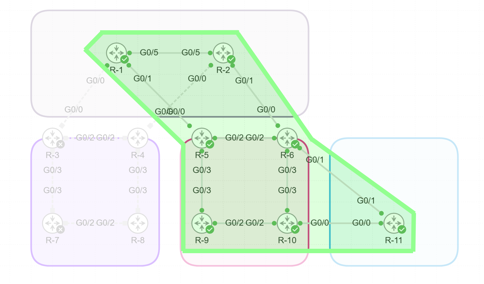
In this example I will focus on the Top and Right side of the ISIS topology, in combination with the OSPF Router.
Configuration L2 Routers (R1 & R2)
==== R1 & R2  (L2)

hostname R2
interface Loopback0
 ipv4 address 2.2.2.2 255.255.255.255
!
interface GigabitEthernet0/0/0/0
 ipv4 address 10.2.4.2 255.255.255.0
!
interface GigabitEthernet0/0/0/1
 ipv4 address 10.2.6.2 255.255.255.0
!
interface GigabitEthernet0/0/0/5
 ipv4 address 10.1.2.2 255.255.255.0
!
router isis 1
 is-type level-2-only
 net 49.000.0000.0000.0002.00
 address-family ipv4 unicast
  metric-style wide
 !
 interface Loopback0
  circuit-type level-2-only
  address-family ipv4 unicast
  !
 !
 interface GigabitEthernet0/0/0/0
  circuit-type level-2-only
  address-family ipv4 unicast
  !
 !
 interface GigabitEthernet0/0/0/1
  circuit-type level-2-only
  address-family ipv4 unicast
  !
 !
 interface GigabitEthernet0/0/0/2
  circuit-type level-2-only
  address-family ipv4 unicast
  !
 !
 interface GigabitEthernet0/0/0/5
  circuit-type level-2-only
  address-family ipv4 unicast
  !
 !
!
end
Configuration L1/L2 Routers (R6 & R6)
==== R3,R4,R5,R6  (L1/L2)

hostname R6
!
interface Loopback0
 ipv4 address 6.6.6.6 255.255.255.255
!
interface GigabitEthernet0/0/0/0
 ipv4 address 10.2.6.6 255.255.255.0
!
interface GigabitEthernet0/0/0/1
 ipv4 address 10.6.11.6 255.255.255.0
!
interface GigabitEthernet0/0/0/2
 ipv4 address 10.5.6.6 255.255.255.0
!
interface GigabitEthernet0/0/0/3
 ipv4 address 10.6.10.6 255.255.255.0
!
router isis 1
 net 49.001.0000.0000.0006.00
 address-family ipv4 unicast
  metric-style wide
!
 interface Loopback0
  passive
  address-family ipv4 unicast
  !
 !
 interface GigabitEthernet0/0/0/0
  circuit-type level-2-only
  address-family ipv4 unicast
  !
 !
 interface GigabitEthernet0/0/0/2
  address-family ipv4 unicast
  !
 !
 interface GigabitEthernet0/0/0/3
  circuit-type level-1
  address-family ipv4 unicast
  !
 !
!

========== OSPF only on R6 to R11

router ospf 1
 area 0
  interface GigabitEthernet0/0/0/1
   network point-to-point
  !
 !
!
Configuration L1 Routers (R9 & R10)
==== R7,R8,R9,R10  (L1)

hostname R10
interface Loopback0
 ip address 10.10.10.10 255.255.255.255
 ip router isis 1
 isis circuit-type level-1
!
interface GigabitEthernet0/0
 ip address 10.10.11.10 255.255.255.0
 ip ospf network point-to-point
 ip ospf 1 area 0
 media-type rj45
!
interface GigabitEthernet0/2
 ip address 10.9.10.10 255.255.255.0
 ip router isis 1
 isis circuit-type level-1
!
interface GigabitEthernet0/3
 ip address 10.6.10.10 255.255.255.0
 ip router isis 1
 isis circuit-type level-1
!
router isis 1
 net 49.0001.0000.0000.0010.00
 is-type level-1
 metric-style wide
!
router ospf 1
 router-id 10.10.10.10
!
Configuration OSPF Router (R11)
==== R11

hostname R11

interface Loopback0
 ip address 11.11.11.11 255.255.255.255
 ip ospf 1 area 0
!
interface GigabitEthernet0/0
 ip address 10.10.11.11 255.255.255.0
 ip ospf network point-to-point
 ip ospf 1 area 0
!
interface GigabitEthernet0/1
 ip address 10.6.11.11 255.255.255.0
 ip ospf network point-to-point
 ip ospf 1 area 0
!
router ospf 1
 router-id 11.11.11.11
 redistribute connected subnets

==== These are subnets we are using for redistribution into IS-IS

!
interface Loopback100
 ip address 100.130.1.1 255.255.255.0
!
interface Loopback101
 ip address 100.130.2.1 255.255.255.0
!
interface Loopback102
 ip address 100.130.3.1 255.255.255.0
!
Router Verifications
Verification L2 Routers (R1 & R2)
==== R1 & R2  (L2)

RP/0/0/CPU0:R2#sh isis interface brief

IS-IS 1 Interfaces
    Interface      All     Adjs    Adj Topos  Adv Topos  CLNS   MTU    Prio
                   OK    L1   L2    Run/Cfg    Run/Cfg                L1   L2
-----------------  ---  ---------  ---------  ---------  ----  ----  --------
Lo0                Yes    -    0      1/1        1/1     Up    1500    -    -
Gi0/0/0/0          No     -    -      0/1        0/1     Down  1497    -    -
Gi0/0/0/1          Yes    -    1      1/1        1/1     Up    1497    -   64
Gi0/0/0/2          No     -    -      0/1        0/1     Down  1497    -    -
Gi0/0/0/5          Yes    -    1*     1/1        1/1     Up    1497    -   64


RP/0/0/CPU0:R2#show isis neighbors
IS-IS 1 neighbors:
System Id      Interface        SNPA           State Holdtime Type IETF-NSF
R1             Gi0/0/0/5        5254.000e.f99f Up    26       L2   Capable
R6             Gi0/0/0/1        5254.001e.fa78 Up    9        L2   Capable
Total neighbor count: 2


RP/0/0/CPU0:R2#show isis protocol
IS-IS Router: 1
  System Id: 0000.0000.0002
  Instance Id: 0
  IS Levels: level-2-only
  Manual area address(es):
    49.0000
  Routing for area address(es):
    49.0000
  Non-stop forwarding: Disabled
  Most recent startup mode: Cold Restart
  TE connection status: Down
  Topologies supported by IS-IS:
    IPv4 Unicast
      Level-2
        Metric style (generate/accept): Wide/Wide
        Metric: 10
        ISPF status: Disabled
      No protocols redistributed
      Distance: 115
      Advertise Passive Interface Prefixes Only: No
  SRLB allocated: 0 - 0
  SRGB not allocated
  Interfaces supported by IS-IS:
    Loopback0 is running actively (active in configuration)
    GigabitEthernet0/0/0/0 is disabled (active in configuration)
    GigabitEthernet0/0/0/1 is running actively (active in configuration)
    GigabitEthernet0/0/0/2 is disabled (active in configuration)
    GigabitEthernet0/0/0/5 is running actively (active in configuration)

RP/0/0/CPU0:R2#sh ip route
Codes: C - connected, S - static, R - RIP, B - BGP, (>) - Diversion path
       D - EIGRP, EX - EIGRP external, O - OSPF, IA - OSPF inter area
       N1 - OSPF NSSA external type 1, N2 - OSPF NSSA external type 2
       E1 - OSPF external type 1, E2 - OSPF external type 2, E - EGP
       i - ISIS, L1 - IS-IS level-1, L2 - IS-IS level-2
       ia - IS-IS inter area, su - IS-IS summary null, * - candidate default
       U - per-user static route, o - ODR, L - local, G  - DAGR, l - LISP
       A - access/subscriber, a - Application route
       M - mobile route, r - RPL, t - Traffic Engineering, (!) - FRR Backup path

Gateway of last resort is not set

i L2 1.1.1.1/32 [115/10] via 10.1.2.1, 02:44:43, GigabitEthernet0/0/0/5
L    2.2.2.2/32 is directly connected, 03:16:36, Loopback0
i L2 5.5.5.5/32 [115/20] via 10.2.6.6, 02:44:34, GigabitEthernet0/0/0/1
                [115/20] via 10.1.2.1, 02:44:34, GigabitEthernet0/0/0/5
i L2 6.6.6.6/32 [115/10] via 10.2.6.6, 02:44:43, GigabitEthernet0/0/0/1
i L2 9.9.9.9/32 [115/40] via 10.2.6.6, 02:44:34, GigabitEthernet0/0/0/1
                [115/40] via 10.1.2.1, 02:44:34, GigabitEthernet0/0/0/5
C    10.1.2.0/24 is directly connected, 02:44:46, GigabitEthernet0/0/0/5
L    10.1.2.2/32 is directly connected, 02:44:46, GigabitEthernet0/0/0/5
i L2 10.1.5.0/24 [115/20] via 10.1.2.1, 02:44:43, GigabitEthernet0/0/0/5
C    10.2.6.0/24 is directly connected, 02:44:46, GigabitEthernet0/0/0/1
L    10.2.6.2/32 is directly connected, 02:44:46, GigabitEthernet0/0/0/1
i L2 10.5.6.0/24 [115/20] via 10.2.6.6, 02:44:43, GigabitEthernet0/0/0/1
i L2 10.5.9.0/24 [115/30] via 10.2.6.6, 02:44:34, GigabitEthernet0/0/0/1
                 [115/30] via 10.1.2.1, 02:44:34, GigabitEthernet0/0/0/5
i L2 10.6.10.0/24 [115/20] via 10.2.6.6, 02:44:43, GigabitEthernet0/0/0/1
i L2 10.6.11.0/24 [115/10] via 10.2.6.6, 02:44:43, GigabitEthernet0/0/0/1
i L2 10.9.10.0/24 [115/30] via 10.2.6.6, 02:44:43, GigabitEthernet0/0/0/1
i L2 10.10.10.10/32 [115/30] via 10.2.6.6, 02:44:43, GigabitEthernet0/0/0/1
i L2 10.10.11.0/24 [115/10] via 10.2.6.6, 02:44:43, GigabitEthernet0/0/0/1
i L2 11.11.11.11/32 [115/10] via 10.2.6.6, 02:44:43, GigabitEthernet0/0/0/1
Verification L1/L2 Routers (R5 & R6)
==== R3,R4,R5,R6  (L1/L2)

RP/0/0/CPU0:R6#sh isis interface brief
IS-IS 1 Interfaces
    Interface      All     Adjs    Adj Topos  Adv Topos  CLNS   MTU    Prio
                   OK    L1   L2    Run/Cfg    Run/Cfg                L1   L2
-----------------  ---  ---------  ---------  ---------  ----  ----  --------
Lo0                Yes    -    -      0/0        1/1     No       -    -    -
Gi0/0/0/0          Yes    -    1*     1/1        1/1     Up    1497    -   64
Gi0/0/0/2          Yes    1    1      1/1        1/1     Up    1497   64   64
Gi0/0/0/3          Yes    1*   -      1/1        1/1     Up    1497   64    -


RP/0/0/CPU0:R6#sh isis neighbors
IS-IS 1 neighbors:
System Id      Interface        SNPA           State Holdtime Type IETF-NSF
R5             Gi0/0/0/2        5254.00d2.8412 Up    9        L1L2 Capable
R10            Gi0/0/0/3        5254.0049.df60 Up    24       L1   Capable
R2             Gi0/0/0/0        5254.0003.35af Up    25       L2   Capable


RP/0/0/CPU0:R6#sh ospf interface brief
* Indicates MADJ interface, (P) Indicates fast detect hold down state
Interfaces for OSPF 1
Interface          PID   Area            IP Address/Mask    Cost  State Nbrs F/C
Gi0/0/0/1          1     0               10.6.11.6/24       1     P2P   1/1


RP/0/0/CPU0:R6#show ospf neighbor
Wed Nov 27 18:38:54.177 UTC

* Indicates MADJ interface
# Indicates Neighbor awaiting BFD session up

Neighbors for OSPF 1

Neighbor ID     Pri   State           Dead Time   Address         Interface
11.11.11.11     1     FULL/  -        00:00:39    10.6.11.11      GigabitEthernet0/0/0/1
    Neighbor is up for 03:18:40

Total neighbor count: 1


RP/0/0/CPU0:R6#sh ip route
Codes: C - connected, S - static, R - RIP, B - BGP, (>) - Diversion path
       D - EIGRP, EX - EIGRP external, O - OSPF, IA - OSPF inter area
       N1 - OSPF NSSA external type 1, N2 - OSPF NSSA external type 2
       E1 - OSPF external type 1, E2 - OSPF external type 2, E - EGP
       i - ISIS, L1 - IS-IS level-1, L2 - IS-IS level-2
       ia - IS-IS inter area, su - IS-IS summary null, * - candidate default
       U - per-user static route, o - ODR, L - local, G  - DAGR, l - LISP
       A - access/subscriber, a - Application route
       M - mobile route, r - RPL, t - Traffic Engineering, (!) - FRR Backup path

Gateway of last resort is not set

i L2 1.1.1.1/32 [115/20] via 10.2.6.2, 02:50:17, GigabitEthernet0/0/0/0
                [115/20] via 10.5.6.5, 02:50:17, GigabitEthernet0/0/0/2
i L2 2.2.2.2/32 [115/20] via 10.2.6.2, 02:50:17, GigabitEthernet0/0/0/0
i L1 5.5.5.5/32 [115/10] via 10.5.6.5, 03:25:19, GigabitEthernet0/0/0/2
L    6.6.6.6/32 is directly connected, 03:25:26, Loopback0
i L1 9.9.9.9/32 [115/30] via 10.5.6.5, 03:25:14, GigabitEthernet0/0/0/2
                [115/30] via 10.6.10.10, 03:25:14, GigabitEthernet0/0/0/3
i L2 10.1.2.0/24 [115/20] via 10.2.6.2, 02:50:17, GigabitEthernet0/0/0/0
i L2 10.1.5.0/24 [115/20] via 10.5.6.5, 02:56:15, GigabitEthernet0/0/0/2
C    10.2.6.0/24 is directly connected, 03:25:26, GigabitEthernet0/0/0/0
L    10.2.6.6/32 is directly connected, 03:25:26, GigabitEthernet0/0/0/0
C    10.5.6.0/24 is directly connected, 03:25:26, GigabitEthernet0/0/0/2
L    10.5.6.6/32 is directly connected, 03:25:26, GigabitEthernet0/0/0/2
i L1 10.5.9.0/24 [115/20] via 10.5.6.5, 03:25:19, GigabitEthernet0/0/0/2
C    10.6.10.0/24 is directly connected, 03:25:26, GigabitEthernet0/0/0/3
L    10.6.10.6/32 is directly connected, 03:25:26, GigabitEthernet0/0/0/3
C    10.6.11.0/24 is directly connected, 03:25:26, GigabitEthernet0/0/0/1
L    10.6.11.6/32 is directly connected, 03:25:26, GigabitEthernet0/0/0/1
i L1 10.9.10.0/24 [115/20] via 10.6.10.10, 03:25:19, GigabitEthernet0/0/0/3
i L1 10.10.10.10/32 [115/20] via 10.6.10.10, 03:25:19, GigabitEthernet0/0/0/3
O    10.10.11.0/24 [110/2] via 10.6.11.11, 03:18:57, GigabitEthernet0/0/0/1
O    11.11.11.11/32 [110/2] via 10.6.11.11, 03:18:57, GigabitEthernet0/0/0/1
Verification L1 Routers (R9 & R10)
==== R7,R8,R9,R10  (L1)

hostname R10
interface Loopback0
 ip address 10.10.10.10 255.255.255.255
 ip router isis 1
 isis circuit-type level-1
!
interface GigabitEthernet0/0
 ip address 10.10.11.10 255.255.255.0
 ip ospf network point-to-point
 ip ospf 1 area 0
 media-type rj45
!
interface GigabitEthernet0/2
 ip address 10.9.10.10 255.255.255.0
 ip router isis 1
 isis circuit-type level-1
!
interface GigabitEthernet0/3
 ip address 10.6.10.10 255.255.255.0
 ip router isis 1
 isis circuit-type level-1
!
router isis 1
 net 49.0001.0000.0000.0010.00
 is-type level-1
 metric-style wide
!
router ospf 1
 router-id 10.10.10.10
!
Verification OSPF Router (R11)
==== R11
R11#sh ip ospf neighbor

Neighbor ID     Pri   State           Dead Time   Address         Interface
10.10.10.10       0   FULL/  -        00:00:38    10.10.11.10     GigabitEthernet0/0
6.6.6.6           0   FULL/  -        00:00:37    10.6.11.6       GigabitEthernet0/1

R11#sh ip route
Codes: L - local, C - connected, S - static, R - RIP, M - mobile, B - BGP
       D - EIGRP, EX - EIGRP external, O - OSPF, IA - OSPF inter area
       N1 - OSPF NSSA external type 1, N2 - OSPF NSSA external type 2
       E1 - OSPF external type 1, E2 - OSPF external type 2
       i - IS-IS, su - IS-IS summary, L1 - IS-IS level-1, L2 - IS-IS level-2
       ia - IS-IS inter area, * - candidate default, U - per-user static route
       o - ODR, P - periodic downloaded static route, H - NHRP, l - LISP
       a - application route
       + - replicated route, % - next hop override, p - overrides from PfR

Gateway of last resort is not set

C        10.6.11.0/24 is directly connected, GigabitEthernet0/1
L        10.6.11.11/32 is directly connected, GigabitEthernet0/1
C        10.10.11.0/24 is directly connected, GigabitEthernet0/0
L        10.10.11.11/32 is directly connected, GigabitEthernet0/0
      11.0.0.0/32 is subnetted, 1 subnets
C        11.11.11.11 is directly connected, Loopback0
IS-IS Redistribution
When redistributing routes into IS-IS, the impact depends on whether the routes are injected into L1, L2, or both levels (L1-2). Each IS-IS level utilizes its own Link-State Database (LSDB) to store and manage routing information. The separation of LSDBs is fundamental to the hierarchical design of IS-IS, supporting scalability and clear demarcation between intra-area (Level 1) and inter-area (Level 2) routing.
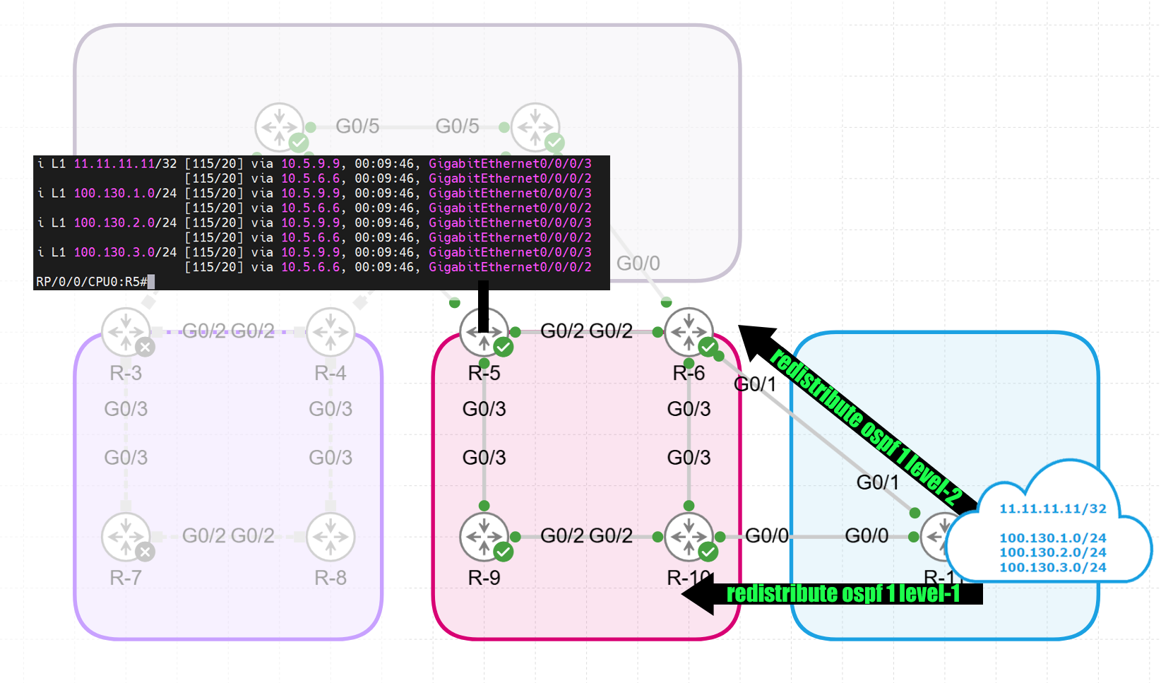
In this example I will redistribute the following prefixes from the OSPF router:
- 11.11.11.11/32 (loopback)
- 100.130.1.0/24
- 100.130.2.0/24
- 100.130.3.0/24
The 100.130.x.y subnets are going to be summarized in section 7.
Verification of the L1 and L2 database on R6:
RP/0/0/CPU0:R6#sh isis database R6.00-00 detail

IS-IS 1 (Level-1) Link State Database
LSPID                 LSP Seq Num  LSP Checksum  LSP Holdtime  ATT/P/OL
R6.00-00            * 0x00000067   0x13c1        502             1/0/0
  Area Address:   49.0001
  Metric: 10         IS-Extended R5.03
  Metric: 10         IS-Extended R6.05
  NLPID:          0xcc
  IP Address:     6.6.6.6
  Metric: 0          IP-Extended 6.6.6.6/32
  Metric: 10         IP-Extended 10.5.6.0/24
  Metric: 10         IP-Extended 10.6.10.0/24
  Metric: 0          IP-Extended 10.6.11.0/24
  Metric: 0          IP-Extended 10.10.11.0/24
  Metric: 0          IP-Extended 11.11.11.11/32
  Metric: 0          IP-Extended 100.130.1.0/24
  Metric: 0          IP-Extended 100.130.2.0/24
  Metric: 0          IP-Extended 100.130.3.0/24
  Hostname:       R6

IS-IS 1 (Level-2) Link State Database
LSPID                 LSP Seq Num  LSP Checksum  LSP Holdtime  ATT/P/OL
R6.00-00            * 0x0000006b   0x263b        828             0/0/0
  Area Address:   49.0001
  Metric: 10         IS-Extended R5.03
  Metric: 10         IS-Extended R6.01
  NLPID:          0xcc
  IP Address:     6.6.6.6
  Metric: 10         IP-Extended 5.5.5.5/32
  Metric: 0          IP-Extended 6.6.6.6/32
  Metric: 30         IP-Extended 9.9.9.9/32
  Metric: 10         IP-Extended 10.2.6.0/24
  Metric: 10         IP-Extended 10.5.6.0/24
  Metric: 20         IP-Extended 10.5.9.0/24
  Metric: 10         IP-Extended 10.6.10.0/24
  Metric: 20         IP-Extended 10.9.10.0/24
  Metric: 20         IP-Extended 10.10.10.10/32
  Metric: 10         IP-Extended 10.10.11.0/24
  Hostname:       R6
Redistribution into IS-IS Level-1
router isis 1 address-family ipv4 unicast redistribute ospf 1 level-1
Redistributing routes into Level 1 (L1) confines those routes to the local IS-IS area. These redistributed routes are advertised to all L1 routers within the same area, ensuring that all routers in the local topology have visibility into them. However, these routes do not propagate beyond the boundaries of the area, keeping them invisible to other areas in the IS-IS domain.
When an L1 router needs to communicate with destinations outside its area, it typically relies on a default route provided by an L1-2 router. This approach is particularly useful for injecting external routes that are relevant only within a specific area. By limiting the scope of redistribution to L1, the L2 topology is kept cleaner, as unnecessary external routes do not pollute the L2 backbone.
==== R6

router isis 1
 address-family ipv4 unicast
  redistribute ospf 1 level-1

==== R10 (LEVEL 1 Router)

R10#sh route

-- Redistributed OSPF routes from R6

i L1     11.11.11.11 [115/10] via 10.6.10.6, 00:17:46, GigabitEthernet0/3
      100.0.0.0/24 is subnetted, 3 subnets
i L1     100.130.1.0 [115/10] via 10.6.10.6, 00:17:46, GigabitEthernet0/3
i L1     100.130.2.0 [115/10] via 10.6.10.6, 00:17:46, GigabitEthernet0/3
i L1     100.130.3.0 [115/10] via 10.6.10.6, 00:17:46, GigabitEthernet0/3

==== R2 (LEVEL 2 Router - L1 propagated into L2)

i L2 11.11.11.11/32 [115/30] via 10.2.6.6, 00:23:16, GigabitEthernet0/0/0/1
                    [115/30] via 10.1.2.1, 00:23:16, GigabitEthernet0/0/0/5
i L2 100.130.1.0/24 [115/30] via 10.2.6.6, 01:33:23, GigabitEthernet0/0/0/1
                    [115/30] via 10.1.2.1, 01:33:23, GigabitEthernet0/0/0/5
i L2 100.130.2.0/24 [115/30] via 10.2.6.6, 01:33:23, GigabitEthernet0/0/0/1
                    [115/30] via 10.1.2.1, 01:33:23, GigabitEthernet0/0/0/5
i L2 100.130.3.0/24 [115/30] via 10.2.6.6, 01:33:23, GigabitEthernet0/0/0/1
                    [115/30] via 10.1.2.1, 01:33:23, GigabitEthernet0/0/0/5
Redistribution into IS-IS Level-2
router isis 1 address-family ipv4 unicast redistribute ospf 1 level-2
When routes are redistributed into Level 2 (L2), they are injected into the IS-IS backbone and become accessible across the entire IS-IS domain. These routes are propagated by L2 routers, ensuring that they are visible in all areas that participate in L2 routing. This form of redistribution is most effective when the routes need to be available across multiple areas or the entire domain. It is often employed when connecting different IS-IS areas or importing routes from external routing domains into IS-IS. Since L2 serves as the backbone for inter-area communication, routes injected at this level achieve global visibility within the IS-IS domain, making L2 redistribution ideal for sharing broadly relevant routing information.
==== R6

router isis 1
 address-family ipv4 unicast
  redistribute ospf 1 level-2

==== R2

RP/0/0/CPU0:R2#sh route isis
Thu Nov 28 10:26:59.234 UTC

i L2 1.1.1.1/32 [115/10] via 10.1.2.1, 18:38:02, GigabitEthernet0/0/0/5
i L2 5.5.5.5/32 [115/20] via 10.1.2.1, 18:37:54, GigabitEthernet0/0/0/5
                [115/20] via 10.2.6.6, 18:37:54, GigabitEthernet0/0/0/1
i L2 6.6.6.6/32 [115/10] via 10.2.6.6, 18:38:02, GigabitEthernet0/0/0/1
i L2 9.9.9.9/32 [115/40] via 10.1.2.1, 18:37:54, GigabitEthernet0/0/0/5
                [115/40] via 10.2.6.6, 18:37:54, GigabitEthernet0/0/0/1
i L2 10.1.5.0/24 [115/20] via 10.1.2.1, 18:38:02, GigabitEthernet0/0/0/5
i L2 10.5.6.0/24 [115/20] via 10.2.6.6, 18:38:02, GigabitEthernet0/0/0/1
i L2 10.5.9.0/24 [115/30] via 10.1.2.1, 18:37:54, GigabitEthernet0/0/0/5
                 [115/30] via 10.2.6.6, 18:37:54, GigabitEthernet0/0/0/1
i L2 10.6.10.0/24 [115/20] via 10.2.6.6, 18:38:02, GigabitEthernet0/0/0/1
i L2 10.6.11.0/24 [115/30] via 10.1.2.1, 14:57:32, GigabitEthernet0/0/0/5
                  [115/30] via 10.2.6.6, 14:57:32, GigabitEthernet0/0/0/1
i L2 10.9.10.0/24 [115/30] via 10.2.6.6, 18:38:02, GigabitEthernet0/0/0/1
i L2 10.10.10.10/32 [115/30] via 10.2.6.6, 18:38:02, GigabitEthernet0/0/0/1
i L2 10.10.11.0/24 [115/30] via 10.1.2.1, 14:57:32, GigabitEthernet0/0/0/5
                   [115/30] via 10.2.6.6, 14:57:32, GigabitEthernet0/0/0/1

==== L2 routes from OSPF

i L2 11.11.11.11/32 [115/30] via 10.1.2.1, 14:57:32, GigabitEthernet0/0/0/5
                    [115/30] via 10.2.6.6, 14:57:32, GigabitEthernet0/0/0/1
i L2 100.130.1.0/24 [115/30] via 10.1.2.1, 16:07:39, GigabitEthernet0/0/0/5
                    [115/30] via 10.2.6.6, 16:07:39, GigabitEthernet0/0/0/1
i L2 100.130.2.0/24 [115/30] via 10.1.2.1, 16:07:39, GigabitEthernet0/0/0/5
                    [115/30] via 10.2.6.6, 16:07:39, GigabitEthernet0/0/0/1
i L2 100.130.3.0/24 [115/30] via 10.1.2.1, 16:07:39, GigabitEthernet0/0/0/5
                    [115/30] via 10.2.6.6, 16:07:39, GigabitEthernet0/0/0/1
Redistribution into IS-IS Level-1-2
router isis 1 address-family ipv4 unicast redistribute ospf 1 level-1-2
Redistribution into Level 1-2 (L1-2) involves injecting routes into both the L1 and L2 levels simultaneously. In this scenario, the routes are advertised locally within the area (L1) and across the IS-IS backbone (L2). L1-2 routers play a critical role here, functioning as intermediaries to ensure that routes are visible both intra-area and inter-area. This dual-level redistribution is particularly useful for scenarios where routes need comprehensive visibility, both within their originating area and across the broader IS-IS domain. It is commonly used when transitioning between areas or when flexibility in route propagation is required. By ensuring that redistributed routes reach both local and global scopes, L1-2 redistribution provides a balanced and versatile approach to route injection.
When both L1 and L2 routes are available, IS-IS path selection takes place.
==== R6

router isis 1
 address-family ipv4 unicast
  redistribute ospf 1 level-1-2


==== L2 routes from OSPF

i L2 11.11.11.11/32 [115/30] via 10.1.2.1, 14:57:32, GigabitEthernet0/0/0/5
                    [115/30] via 10.2.6.6, 14:57:32, GigabitEthernet0/0/0/1
i L2 100.130.1.0/24 [115/30] via 10.1.2.1, 16:07:39, GigabitEthernet0/0/0/5
                    [115/30] via 10.2.6.6, 16:07:39, GigabitEthernet0/0/0/1
i L2 100.130.2.0/24 [115/30] via 10.1.2.1, 16:07:39, GigabitEthernet0/0/0/5
                    [115/30] via 10.2.6.6, 16:07:39, GigabitEthernet0/0/0/1
i L2 100.130.3.0/24 [115/30] via 10.1.2.1, 16:07:39, GigabitEthernet0/0/0/5
                    [115/30] via 10.2.6.6, 16:07:39, GigabitEthernet0/0/0/1
IS-IS Path Selection
In IS-IS path selection, when both Level 1 (L1) and Level 2 (L2) routes are available, the protocol prioritizes the level of the route based on the network topology and routing logic;
-
Intra-area (L1) Preference: If a destination is reachable through an L1 route, IS-IS will prioritize this route for intra-area traffic, as L1 routes are designed for communication within the same area. The L1 route is considered more specific because it deals directly with local area routing.
-
Inter-area (L2) Use: If the destination is not reachable within the local area, IS-IS will look for an L2 route. L2 routes provide connectivity between areas via the L2 backbone. This hierarchical approach ensures scalability and reduces routing complexity within individual areas.
-
Route Selection Criteria: Within each level, IS-IS selects routes based on metrics. The protocol uses a cost-based metric system, where the path with the lowest accumulated cost is preferred. If multiple routes have the same cost, tie-breaking mechanisms such as equal-cost multipath (ECMP) may be employed.
-
L1/L2 Routers: Routers configured as L1/L2 can advertise default routes between levels, enabling L1 routers to forward inter-area traffic to an L2 router when no L1 path exists.
This selection process allows IS-IS to handle both localized and hierarchical routing efficiently while maintaining clear boundaries between intra-area and inter-area traffic.
IS-IS Route Summarization
Route summarization is crucial for ensuring scalability in IS-IS networks. It addresses two key challenges: excessively large routing tables and frequent flooding of link-state updates across the autonomous system (AS). When a route is withdrawn in one area, routers in other areas may need to recalculate shortest paths, increasing processing overhead. To mitigate this and reduce the size of the routing database, summarization can be configured at level boundaries.
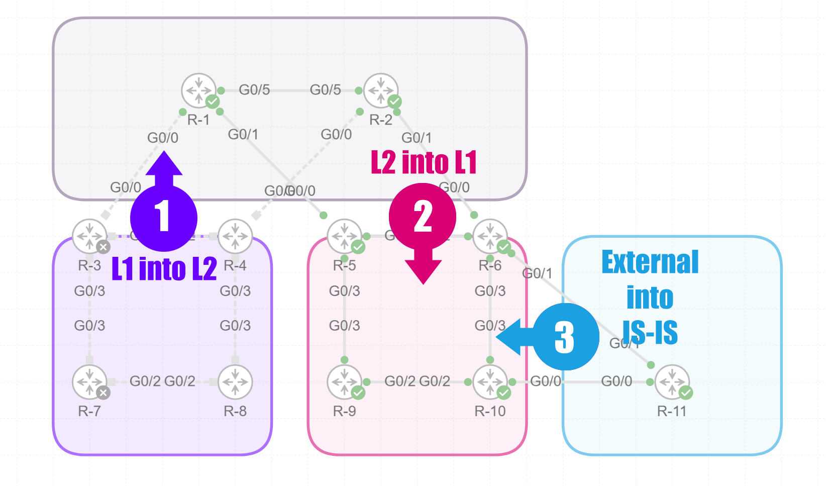
IS-IS Summarization locations
These are the 3 locations where you can summarize routes within an IS-IS domain.
Option 1: Summarize Routes Leaked from L1 into L2
In IS-IS, routes learned in Level 1 (intra-area) can be selectively leaked into Level 2 (inter-area) to allow Level 2 routers to access destinations in the Level 1 area. Summarizing these leaked routes reduces the number of individual prefixes advertised into the Level 2 domain. This is particularly useful for minimizing the size of the Level 2 routing table and reducing the scope of link-state updates, ensuring efficient network operation while maintaining connectivity between areas.
Option 2: Summarize Routes Leaked from L2 into L1
Routes learned in Level 2 can also be leaked into Level 1 to allow intra-area routers to access inter-area or external destinations. Summarizing these routes ensures that only aggregate prefixes are advertised back into the Level 1 domain. This helps to prevent Level 1 routers from being overwhelmed by unnecessary route details, maintaining simplicity and efficiency within the Level 1 routing tables.
Option 3: Summarize Imported Routes
When routes are imported into the IS-IS domain from external sources, such as other routing protocols, they can be summarized to limit the number of prefixes injected into the IS-IS database. Summarization at this stage helps to contain external routing information, reducing processing and memory requirements for IS-IS routers and preventing external changes from causing excessive link-state protocol flooding within the IS-IS domain.
IS-IS Summarization configuration
In this example I will use option 3 and redistribute the following prefixes from the OSPF router:
- 100.130.1.0/24 (OSPF)
- 100.130.2.0/24 (OSPF)
- 100.130.3.0/24 (OSPF)
- 100.130.0.0/16 (IS-IS Summary)
R6 will then make a Null0 route with the summarized prefix to advertise in the IS-IS domain.
==== R6

router isis 1
 net 49.001.0000.0000.0006.00
 address-family ipv4 unicast
  metric-style wide
  summary-prefix 100.130.0.0/16 level 2    = summarize the route and add in the L2 LSDB
  redistribute ospf 1 level-2
 !

======

RP/0/0/CPU0:R6#sh route isis
Thu Nov 28 14:23:31.218 UTC

i L2 1.1.1.1/32 [115/20] via 10.5.6.5, 22:34:36, GigabitEthernet0/0/0/2
                [115/20] via 10.2.6.2, 22:34:36, GigabitEthernet0/0/0/0
i L2 2.2.2.2/32 [115/20] via 10.2.6.2, 22:34:36, GigabitEthernet0/0/0/0
i L1 5.5.5.5/32 [115/10] via 10.6.10.10, 01:03:09, GigabitEthernet0/0/0/3
                [115/10] via 10.5.6.5, 01:03:09, GigabitEthernet0/0/0/2
i L1 9.9.9.9/32 [115/10] via 10.6.10.10, 01:03:09, GigabitEthernet0/0/0/3
i L2 10.1.2.0/24 [115/20] via 10.2.6.2, 22:34:36, GigabitEthernet0/0/0/0
i L2 10.1.5.0/24 [115/20] via 10.5.6.5, 22:40:33, GigabitEthernet0/0/0/2
i L1 10.5.9.0/24 [115/10] via 10.6.10.10, 01:03:09, GigabitEthernet0/0/0/3
i L1 10.9.10.0/24 [115/20] via 10.6.10.10, 23:09:37, GigabitEthernet0/0/0/3
i L1 10.10.10.10/32 [115/20] via 10.6.10.10, 23:09:37, GigabitEthernet0/0/0/3
i su 100.130.0.0/16 [115/0] via 0.0.0.0, 00:03:26, Null0                          = Null0 route


su - IS-IS summary null
IS-IS Summarization verification
L1-2 router R5:
==== R5 (L1-2)

RP/0/0/CPU0:R5#sh route isis
Thu Nov 28 14:24:20.564 UTC

i L2 1.1.1.1/32 [115/10] via 10.1.5.1, 22:50:09, GigabitEthernet0/0/0/0
i L2 2.2.2.2/32 [115/30] via 10.5.6.6, 22:35:24, GigabitEthernet0/0/0/2
                [115/30] via 10.1.5.1, 22:35:24, GigabitEthernet0/0/0/0
i L1 6.6.6.6/32 [115/10] via 10.5.6.6, 23:10:30, GigabitEthernet0/0/0/2
i L1 9.9.9.9/32 [115/20] via 10.5.9.9, 01:03:58, GigabitEthernet0/0/0/3
                [115/20] via 10.5.6.6, 01:03:58, GigabitEthernet0/0/0/2
i L2 10.1.2.0/24 [115/20] via 10.1.5.1, 22:50:09, GigabitEthernet0/0/0/0
i L1 10.2.6.0/24 [115/20] via 10.5.9.9, 01:03:58, GigabitEthernet0/0/0/3
                 [115/20] via 10.5.6.6, 01:03:58, GigabitEthernet0/0/0/2
i L1 10.6.10.0/24 [115/20] via 10.5.6.6, 23:10:30, GigabitEthernet0/0/0/2
i L1 10.6.11.0/24 [115/20] via 10.5.9.9, 01:03:58, GigabitEthernet0/0/0/3
                  [115/20] via 10.5.6.6, 01:03:58, GigabitEthernet0/0/0/2
i L1 10.9.10.0/24 [115/20] via 10.5.9.9, 23:13:28, GigabitEthernet0/0/0/3
i L1 10.10.10.10/32 [115/30] via 10.5.9.9, 23:10:24, GigabitEthernet0/0/0/3
                    [115/30] via 10.5.6.6, 23:10:24, GigabitEthernet0/0/0/2
i L1 10.10.11.0/24 [115/20] via 10.5.9.9, 01:03:58, GigabitEthernet0/0/0/3
                   [115/20] via 10.5.6.6, 01:03:58, GigabitEthernet0/0/0/2
i L1 11.11.11.11/32 [115/20] via 10.5.9.9, 01:03:58, GigabitEthernet0/0/0/3
                    [115/20] via 10.5.6.6, 01:03:58, GigabitEthernet0/0/0/2

i L2 100.130.0.0/16 [115/10] via 10.5.6.6, 00:04:14, GigabitEthernet0/0/0/2  = Summary Route
L2 router R2:
==== R2 (L2)

RP/0/0/CPU0:R2#sh route isis
Thu Nov 28 14:25:16.035 UTC

i L2 1.1.1.1/32 [115/10] via 10.1.2.1, 22:36:19, GigabitEthernet0/0/0/5
i L2 5.5.5.5/32 [115/20] via 10.1.2.1, 00:05:09, GigabitEthernet0/0/0/5
                [115/20] via 10.2.6.6, 00:05:09, GigabitEthernet0/0/0/1
i L2 6.6.6.6/32 [115/10] via 10.2.6.6, 22:36:19, GigabitEthernet0/0/0/1
i L2 9.9.9.9/32 [115/20] via 10.2.6.6, 00:05:09, GigabitEthernet0/0/0/1
i L2 10.1.5.0/24 [115/20] via 10.1.2.1, 22:36:19, GigabitEthernet0/0/0/5
i L2 10.5.6.0/24 [115/20] via 10.2.6.6, 22:36:19, GigabitEthernet0/0/0/1
i L2 10.5.9.0/24 [115/20] via 10.2.6.6, 00:05:09, GigabitEthernet0/0/0/1
i L2 10.6.10.0/24 [115/20] via 10.2.6.6, 22:36:19, GigabitEthernet0/0/0/1
i L2 10.6.11.0/24 [115/10] via 10.2.6.6, 01:05:07, GigabitEthernet0/0/0/1
i L2 10.9.10.0/24 [115/30] via 10.2.6.6, 22:36:19, GigabitEthernet0/0/0/1
i L2 10.10.10.10/32 [115/30] via 10.2.6.6, 22:36:19, GigabitEthernet0/0/0/1
i L2 10.10.11.0/24 [115/10] via 10.2.6.6, 01:08:08, GigabitEthernet0/0/0/1
i L2 11.11.11.11/32 [115/10] via 10.2.6.6, 01:08:08, GigabitEthernet0/0/0/1

i L2 100.130.0.0/16 [115/10] via 10.2.6.6, 00:05:09, GigabitEthernet0/0/0/1  = Summary Route
