MPLS – Traffic Engineering (MPLS-TE) Lab


What is MPLS Traffic Engineering (MPLS-TE)?


MPLS Traffic Engineering (MPLS-TE) is a technology that enhances the capabilities of MPLS (Multiprotocol Label Switching) to enable more granular control over traffic flow within a network. This is achieved by manipulating traffic paths to optimize resource usage, avoid congestion, and meet specific service requirements, like bandwidth guarantees or low latency.
Traffic engineering refers to the practice of optimizing the flow of network traffic in a way that ensures efficient use of network resources, avoids congestion, and achieves better overall performance. In traditional IP networks, traffic generally follows the shortest path, which can lead to suboptimal usage of network capacity and congestion. MPLS-TE allows operators to move beyond shortest-path routing by explicitly setting up paths through the network that distribute traffic more evenly.

In this lab I’m going to configure  a tunnel to overrule the IGP shortest path and chose a different path.

MPLS Lab Setup


Labs download

Two CML Labs are available for download here.

1 – Lab Pre MPLS-TE config (OSPF, MPLS, LDP).
2 – Lab Post MPLS-TE config (OSPF (With TE), MPLS-TE, LDP, RSVP, Tunnel).

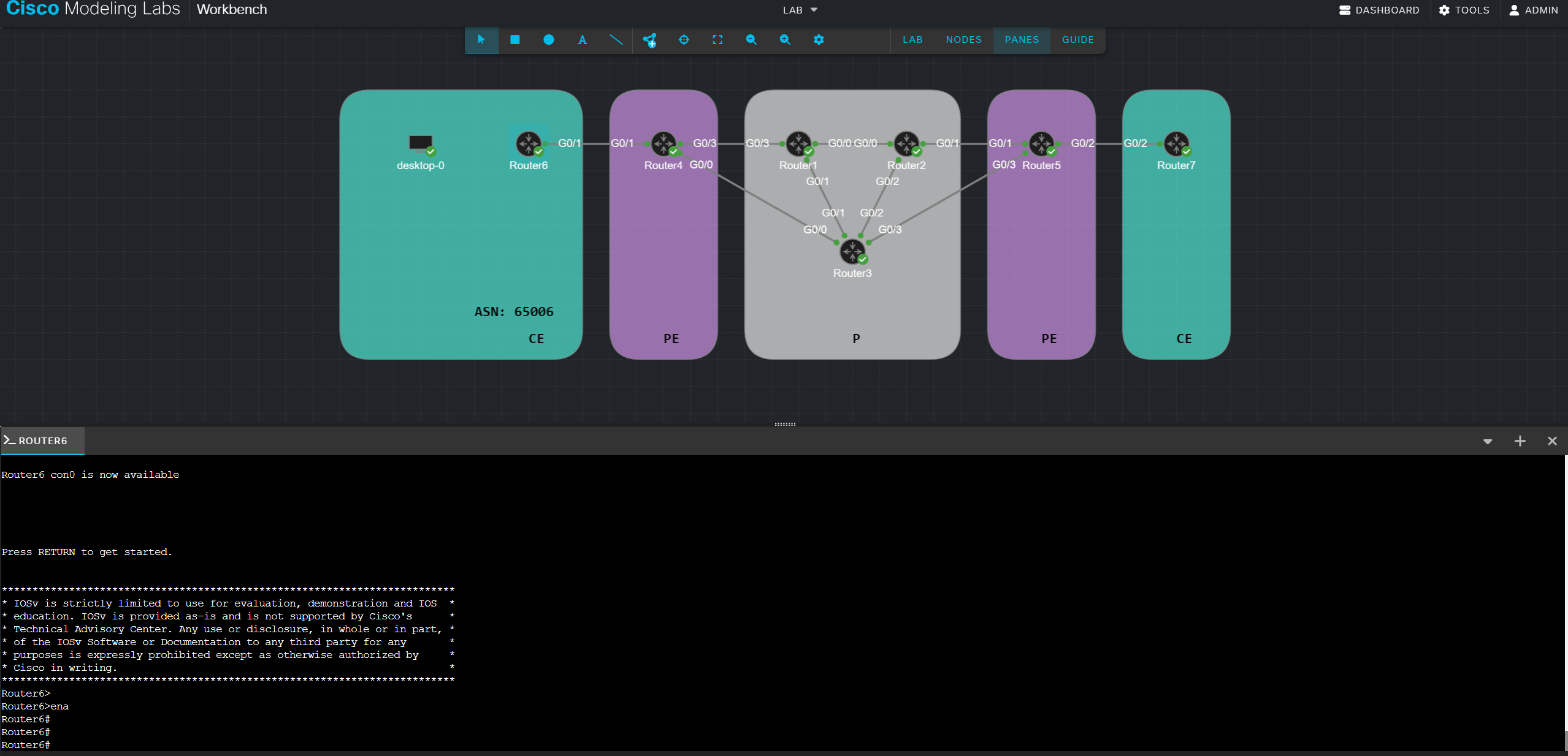
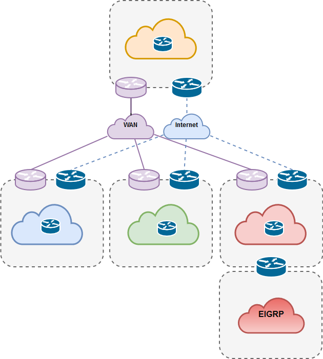
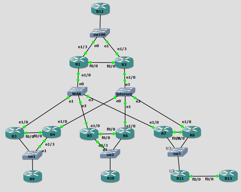
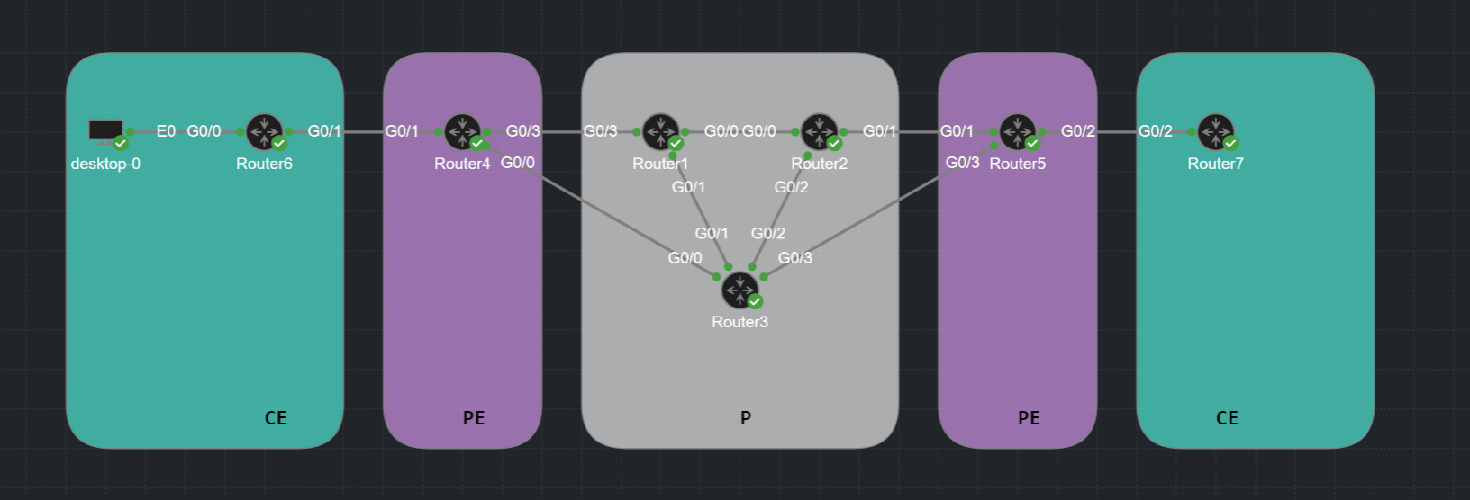
Using Cisco’s Modeling Labs (CML) I build the following MPLS lab using OSPF and LDP neighbor relationships. 

  • 3 x P routers (Router1, Router2, Router3)
  • 2 x PE router (Router4, Router5)
  • 2 x CE router (Router6, Router7)

Default Behaviour
The default traffic flow behaviour from PE Router4 towards PE Router5 will follow the IGP shortest path via P Router3. This path is one hop instead of traversing via Router1+Router2 being two hops away and double the cost.
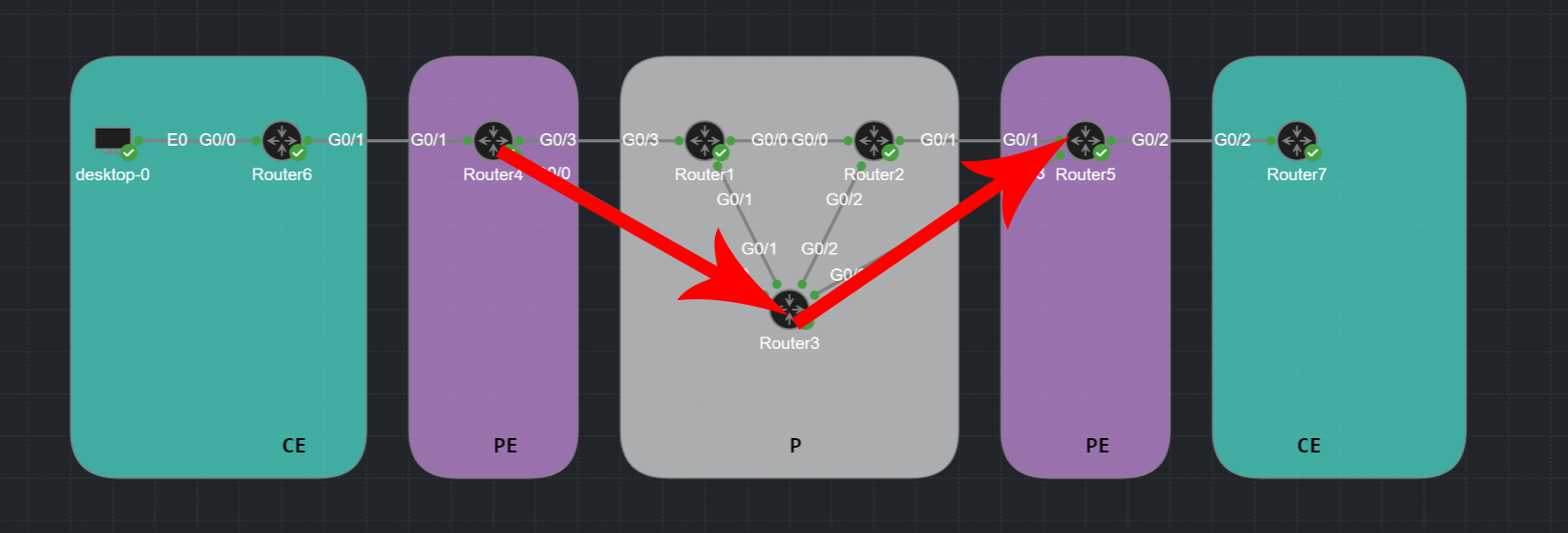
MPLS-TE
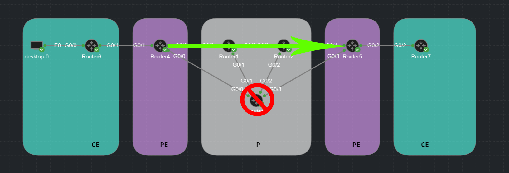
With MPLS-TE we can define a different path via Router1+Router2. 
There can be many reasons why we would want to do this and many ways how we can achieve this. In this Lab I am going to enable MPLS-TE and simply exclude Router3 from our path. 

DeviceFunctionLoopback addressSubnetsLabel Ranges
Router1P Router1.1.1.1/32Gi0/0 10.1.2.1/24
Gi0/1 10.1.3.1/24
Gi0/3 10.1.4.1/24
100-199
Router2P Router2.2.2.2/32Gi0/0 10.1.2.2/24
Gi0/1 10.2.3.2/24
Gi0/3 10.2.4.2/24
200-299
Router3P Router3.3.3.3/32Gi0/0 10.3.4.3/24
Gi0/1 10.1.3.3/24
Gi0/2 10.2.3.3/24
Gi0/3 10.3.5.3/24
300-399
Router4PE Router4.4.4.4/32Gi0/0 10.3.4.4/24
Gi0/1 10.4.6.4/24
Gi0/3 10.1.4.4/24
400-499
Router5PE Router5.5.5.5/32Gi0/1 10.1.5.5/24
Gi0/2 10.5.7.5/24
Gi0/3 10.4.5.5/24
500-599
Router6CE Router6.6.6.6/32Gi0/1 10.4.6.6/24
Gi0/0 192.168.1.1/24
Router7CE Router7.7.7.7/32Gi0/2 10.4.6.6/24
Gi0/0 192.168.2.1/24

IP Addressing:
The point-to-point links are configured with the following IP addressing scheme:

  • 10.<Lowest Router Id>.<Highest Router Id>.<Router Id>./24.”

For example the link between Router1 and Router2 gives on Router1: 10.1.2.1/24 and on Router2: 10.1.2.2/24

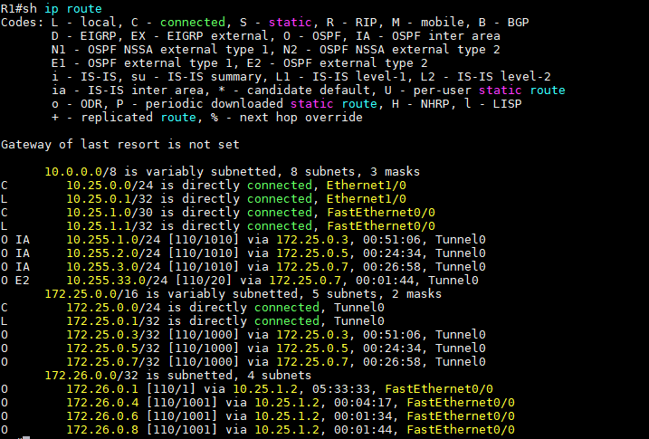
Verification on Router3 (P):

Router3#sh ip ospf neighbor

Neighbor ID     Pri   State           Dead Time   Address         Interface
4.4.4.4           0   FULL/  -        00:00:35    10.3.4.4        GigabitEthernet0/0
1.1.1.1           0   FULL/  -        00:00:38    10.1.3.1        GigabitEthernet0/1
2.2.2.2           0   FULL/  -        00:00:35    10.2.3.2        GigabitEthernet0/2
5.5.5.5           0   FULL/  -        00:00:33    10.3.5.5        GigabitEthernet0/3

Router3#sh mpls interfaces
Interface              IP            Tunnel   BGP Static Operational
GigabitEthernet0/0     Yes (ldp)     No       No  No     Yes
GigabitEthernet0/1     Yes (ldp)     No       No  No     Yes
GigabitEthernet0/2     Yes (ldp)     No       No  No     Yes
GigabitEthernet0/3     Yes (ldp)     No       No  No     Yes

Router3#sh mpls ldp neighbor
    Peer LDP Ident: 5.5.5.5:0; Local LDP Ident 3.3.3.3:0
        TCP connection: 5.5.5.5.57381 - 3.3.3.3.646
        State: Oper; Msgs sent/rcvd: 46/45; Downstream
        Up time: 00:26:54
        LDP discovery sources:
          GigabitEthernet0/3, Src IP addr: 10.3.5.5
        Addresses bound to peer LDP Ident:
          10.2.5.5        5.5.5.5         10.3.5.5
    Peer LDP Ident: 4.4.4.4:0; Local LDP Ident 3.3.3.3:0
        TCP connection: 4.4.4.4.42087 - 3.3.3.3.646
        State: Oper; Msgs sent/rcvd: 44/46; Downstream
        Up time: 00:26:54
        LDP discovery sources:
          GigabitEthernet0/0, Src IP addr: 10.3.4.4
        Addresses bound to peer LDP Ident:
          10.3.4.4        4.4.4.4         10.1.4.4
    Peer LDP Ident: 2.2.2.2:0; Local LDP Ident 3.3.3.3:0
        TCP connection: 2.2.2.2.646 - 3.3.3.3.23943
        State: Oper; Msgs sent/rcvd: 45/45; Downstream
        Up time: 00:26:51
        LDP discovery sources:
          GigabitEthernet0/2, Src IP addr: 10.2.3.2
        Addresses bound to peer LDP Ident:
          10.1.2.2        10.2.5.2        10.2.3.2        2.2.2.2
    Peer LDP Ident: 1.1.1.1:0; Local LDP Ident 3.3.3.3:0
        TCP connection: 1.1.1.1.646 - 3.3.3.3.22044
        State: Oper; Msgs sent/rcvd: 45/45; Downstream
        Up time: 00:26:51
        LDP discovery sources:
          GigabitEthernet0/1, Src IP addr: 10.1.3.1
        Addresses bound to peer LDP Ident:
          10.1.2.1        10.1.3.1        10.1.4.1        1.1.1.1

Router Configurations


P Routers: (Router1, Router2, Router3)

The P routers are configured with the standard subnetting scheme from the table above in combination with OSPF area 0 and LDP as the labelling protocol. The Label range is based on the Router number.

Router1, Router2, Router2#

#---- MPLS ranges and LDP
#---- Modify label range per router
mpls label range 100 199
mpls label protocol ldp
mpls ldp router-id Loopback0 force


#---- Interface configuration with MPLS & OSPF
interface Loopback0
 ip address 1.1.1.1 255.255.255.255
 ip ospf 1 area 0
!
interface GigabitEthernet0/0
 ip address 10.1.2.1 255.255.255.0
 ip ospf network point-to-point
 ip ospf 1 area 0
 mpls ip
!
interface GigabitEthernet0/1
 ip address 10.1.3.1 255.255.255.0
 ip ospf network point-to-point
 ip ospf 1 area 0
 mpls ip
!
interface GigabitEthernet0/3
 ip address 10.1.4.1 255.255.255.0
 ip ospf network point-to-point
 ip ospf 1 area 0
 mpls ip
!

PE Routers: (Router4, Router5)

The PE routers are configured with the standard subnetting scheme from the table above in combination with OSPF area 0 and LDP as the labelling protocol.
Each PE routers has an IBGP session to the other PE router (Router4 <-> Router5) for CE traffic.

Router4 (PE)


# ============= MPLS
mpls label range 400 499
mpls label protocol ldp
mpls ldp router-id Loopback0 force

# ===== Interfaces 

interface Loopback0
 ip address 4.4.4.4 255.255.255.255
 ip ospf 1 area 0
!
interface GigabitEthernet0/0
 ip address 10.3.4.4 255.255.255.0
 ip ospf network point-to-point
 ip ospf 1 area 0
 mpls ip
!
interface GigabitEthernet0/1
 ip vrf forwarding CUST
 ip address 10.4.6.4 255.255.255.0
!
interface GigabitEthernet0/3
 ip address 10.1.4.4 255.255.255.0
 ip ospf network point-to-point
 ip ospf 1 area 0
 mpls ip

# ============= OSPF
router ospf 1
 router-id 4.4.4.4
!

# =========== BGP
router bgp 65000
 template peer-session IBGP
  remote-as 65000
  transport connection-mode active
  update-source Loopback0
 exit-peer-session
 !
 bgp router-id 4.4.4.4
 bgp log-neighbor-changes
 no bgp default ipv4-unicast
 neighbor 5.5.5.5 inherit peer-session IBGP
 neighbor 5.5.5.5 transport connection-mode passive
 !
 address-family ipv4
 exit-address-family
 !
 address-family vpnv4
  neighbor 5.5.5.5 activate
  neighbor 5.5.5.5 send-community extended
  neighbor 5.5.5.5 next-hop-self
 exit-address-family
 !
 address-family ipv4 vrf CUST
  neighbor 10.4.6.6 remote-as 65006
  neighbor 10.4.6.6 activate
  neighbor 10.4.6.6 as-override
 exit-address-family
Router5 (PE)


# ============= MPLS
mpls label range 500 599
mpls label protocol ldp
mpls ldp router-id Loopback0 force

# ===== Interfaces 

interface Loopback0
 ip address 5.5.5.5 255.255.255.255
 ip ospf 1 area 0
!
interface GigabitEthernet0/1
 ip address 10.2.5.5 255.255.255.0
 ip ospf network point-to-point
 ip ospf 1 area 0
 mpls ip
!
interface GigabitEthernet0/2
 ip vrf forwarding CUST
 ip address 10.5.7.5 255.255.255.0
!
interface GigabitEthernet0/3
 ip address 10.3.5.5 255.255.255.0
 ip ospf network point-to-point
 ip ospf 1 area 0
 mpls ip

# ============= OSPF
router ospf 1
 router-id 5.5.5.5
!

# =========== BGP
router bgp 65000
 template peer-session IBGP
  remote-as 65000
  transport connection-mode active
  update-source Loopback0
 exit-peer-session
 !
 bgp router-id 5.5.5.5
 bgp log-neighbor-changes
 no bgp default ipv4-unicast
 neighbor 4.4.4.4 inherit peer-session IBGP

 !
 address-family ipv4
 exit-address-family
 !
 address-family vpnv4
  neighbor 4.4.4.4 activate
  neighbor 4.4.4.4 send-community extended
  neighbor 4.4.4.4 next-hop-self
 exit-address-family
 !
 address-family ipv4 vrf CUST
  neighbor 10.5.7.7 remote-as 65006
  neighbor 10.5.7.7 activate
  neighbor 10.5.7.7 as-override
 exit-address-family

Traceroute between CE routers before TE (R6->R7)

When performing a traceroute between CE routers we see the default IGP shortest path behaviour.
R6 -> R4 -> R3 -> R5 -> R7.
After MPLS-TE we will have created the following path:
R6 -> R4 -> R1 -> R2 -> R5 -> R7.

Router6#traceroute 7.7.7.7 source 6.6.6.6
Type escape sequence to abort.
Tracing the route to 7.7.7.7
VRF info: (vrf in name/id, vrf out name/id)
  1 10.4.6.4 2 msec 3 msec 2 msec
  2 10.3.4.3 [MPLS: Labels 303/511 Exp 0] 10 msec 8 msec 7 msec
  3 10.5.7.5 [AS 65000] [MPLS: Label 511 Exp 0] 9 msec 8 msec 11 msec
  4 10.5.7.7 [AS 65000] 12 msec 12 msec *

MPLS Traffic Engineering Configuration

(more…)

MPLS – Traffic Engineering (MPLS-TE) Options

MPLS, or Multiprotocol Label Switching, is a technique that enhances the speed and efficiency of data flow across complex networks. It operates by adding short path labels to network packets, directing them through a predetermined Label-Switched Path (LSP) rather than traditional IP-based routing. These labels contain all the forwarding information, allowing routers to forward packets based on the label rather than performing complex IP lookups. By simplifying the routing decision process, MPLS can reduce latency, optimize network performance, and enable quality-of-service (QoS) features that guarantee certain levels of bandwidth and prioritize critical applications like voice and video.

MPLS is widely used in service provider networks, supporting technologies like VPNs (Virtual Private Networks) and traffic engineering. In a typical MPLS setup, labels are assigned and stripped at the network’s edge, so the core network can process packets quickly without IP overhead. Additionally, MPLS is adaptable to various network protocols and media, enabling seamless interoperability across different types of infrastructure. By allowing network operators to manage traffic dynamically and reroute around congestion or failures, MPLS ensures greater reliability and robustness, making it a preferred choice for large-scale enterprise and ISP networks.

MPLS Traffic Engineering (MPLS-TE) is a technology that enhances the capabilities of MPLS to enable more granular control over traffic flow within a network. This is achieved by manipulating traffic paths to optimize resource usage, avoid congestion, and meet specific service requirements, like bandwidth guarantees or low latency. Here are key methods by which MPLS-TE can manipulate paths and traffic flow:

MPLS-TE Traffic manipulation options

Explicit Routing with Constraint-Based Routing (CBR)

  • Constraint-based routing allows MPLS-TE to create Label-Switched Paths (LSPs) that follow a specific path through the network, rather than relying on traditional routing protocols.
  • Explicit path setup enables network operators to define exact paths based on link attributes, resource availability, or even administrative preferences, avoiding congested or unreliable links.
  • Constraints can include bandwidth, latency, maximum hop count, and available resources.

! Define an explicit path list for the TE tunnel
Router(config)# ip explicit-path name Path_R1_R3
Router(config-ip-expl-path)# next-address 10.1.1.2  ! IP of Router2
Router(config-ip-expl-path)# next-address 10.1.2.2  ! IP of Router3

! Configure the TE Tunnel
Router(config)# interface Tunnel1
Router(config-if)# ip unnumbered Loopback0
Router(config-if)# tunnel mode mpls traffic-eng
Router(config-if)# tunnel destination 10.1.3.3     ! Destination (Router3)
Router(config-if)# tunnel mpls traffic-eng path-option 1 explicit name Path_R1_R3
Router(config-if)# tunnel mpls traffic-eng bandwidth 1000   ! Set bandwidth constraint
Router(config-if)# no shutdown

Traffic Engineering Database (TED)

  • The TED collects information on the state of the network, such as available bandwidth, link utilization, and link properties.
  • MPLS-TE uses the TED to make dynamic routing decisions based on real-time information, thus selecting paths that avoid congested areas and optimize resource use.

! Enable traffic engineering on OSPF
Router(config)# router ospf 1
Router(config-router)# mpls traffic-eng router-id Loopback0
Router(config-router)# mpls traffic-eng area 0

! Ensure interfaces participate in TE
Router(config)# interface GigabitEthernet0/1
Router(config-if)# ip router ospf 1 area 0
Router(config-if)# mpls traffic-eng tunnels

Resource Reservation with RSVP-TE

  • RSVP-TE (Resource Reservation Protocol with TE extensions) is used to signal and reserve resources along the selected path.
  • This protocol sets up traffic-engineered LSPs (TE LSPs) and reserves the necessary bandwidth to meet quality-of-service (QoS) requirements.
  • With RSVP-TE, MPLS-TE can ensure certain traffic flows (like voice or video) get dedicated resources, reducing packet loss and jitter.

! Enable RSVP globally
Router(config)# mpls traffic-eng tunnels
Router(config)# ip rsvp signaling hello

! Enable RSVP on each interface used by the MPLS-TE tunnel
Router(config)# interface GigabitEthernet0/1
Router(config-if)# ip rsvp bandwidth 10000 1000  ! Interface bandwidth in kbps, reserved bandwidth

! Configure an MPLS-TE tunnel with RSVP
Router(config)# interface Tunnel2
Router(config-if)# ip unnumbered Loopback0
Router(config-if)# tunnel mode mpls traffic-eng
Router(config-if)# tunnel destination 10.1.3.3
Router(config-if)# tunnel mpls traffic-eng bandwidth 2000
Router(config-if)# tunnel mpls traffic-eng path-option 1 dynamic
Router(config-if)# no shutdown

Fast Reroute (FRR)

  • Fast Reroute enables rapid path switching in case of a link or node failure, ensuring minimal disruption.
  • FRR pre-establishes backup LSPs so that traffic can be diverted almost instantaneously in case of an issue on the primary path, enhancing reliability and service continuity.

! Configure fast reroute on the tunnel interface
Router(config)# interface Tunnel2
Router(config-if)# mpls traffic-eng fast-reroute
Router(config-if)# tunnel mpls traffic-eng path-option 1 dynamic
Router(config-if)# no shutdown

Load Balancing and Path Diversity

  • MPLS-TE supports load balancing by distributing traffic across multiple LSPs. This is particularly useful for high-traffic routes that need more bandwidth than a single path can provide.
  • Path diversity ensures that critical data can be split across multiple paths, reducing the risk of a single point of failure and improving network redundancy.

Router(config)# interface Tunnel3
Router(config-if)# ip unnumbered Loopback0
Router(config-if)# tunnel mode mpls traffic-eng
Router(config-if)# tunnel destination 10.1.3.3
Router(config-if)# tunnel mpls traffic-eng path-option 1 dynamic
Router(config-if)# tunnel mpls traffic-eng path-option 2 explicit name Path_R1_R3
Router(config-if)# no shutdown

Bandwidth Guarantees and Traffic Prioritization

  • MPLS-TE can allocate bandwidth to specific traffic flows, ensuring certain types of traffic, like real-time or high-priority data, meet their QoS requirements.
  • Differentiated services (DiffServ) can be implemented within MPLS-TE, allowing traffic prioritization at the LSP level and ensuring high-priority traffic gets preferential treatment.

! Set bandwidth requirement for TE tunnel
Router(config)# interface Tunnel4
Router(config-if)# tunnel mode mpls traffic-eng
Router(config-if)# tunnel destination 10.1.3.3
Router(config-if)# tunnel mpls traffic-eng bandwidth 5000   ! 5000 kbps reserved
Router(config-if)# no shutdown

Administrative Policies and Affinity-Based Routing

  • Administrative policies (affinity or coloring) can be used to prefer or avoid certain links based on the type of traffic.
  • Affinity or link coloring allows paths to be marked for certain traffic types (e.g., customer A’s traffic can only use certain links), enabling more precise traffic segregation and adherence to SLA requirements.

! Define affinity on an interface (e.g., marking it with color 0x10)
Router(config)# interface GigabitEthernet0/2
Router(config-if)# mpls traffic-eng administrative-weight 0x10

! Set affinity for the tunnel
Router(config)# interface Tunnel5
Router(config-if)# tunnel mode mpls traffic-eng
Router(config-if)# tunnel destination 10.1.3.3
Router(config-if)# tunnel mpls traffic-eng path-option 1 dynamic
Router(config-if)# tunnel mpls traffic-eng attribute-flags affinity 0x10
Router(config-if)# no shutdown

Dynamic Path Computation with Path Computation Element (PCE)

  • The Path Computation Element (PCE) is a centralized network component that dynamically computes paths for MPLS-TE LSPs based on network-wide data.
  • PCE enhances scalability and efficiency in large networks by providing real-time, optimized path computation and reducing computational strain on routers.

! Enable PCEP on the router
Router(config)# pce
Router(config-pce)# address ipv4 10.1.4.4
Router(config-pce)# source Loopback0
Router(config-pce)# no shutdown

! Configure the tunnel to use PCE for path computation
Router(config)# interface Tunnel6
Router(config-if)# tunnel mode mpls traffic-eng
Router(config-if)# tunnel destination 10.1.3.3
Router(config-if)# tunnel mpls traffic-eng path-option 1 dynamic pce
Router(config-if)# no shutdown


These examples demonstrate basic configurations for MPLS-TE features. Advanced setups may require customizations based on network architecture, device capabilities, and specific application needs.

Getting started with Cisco Modeling Labs (version 2.7)

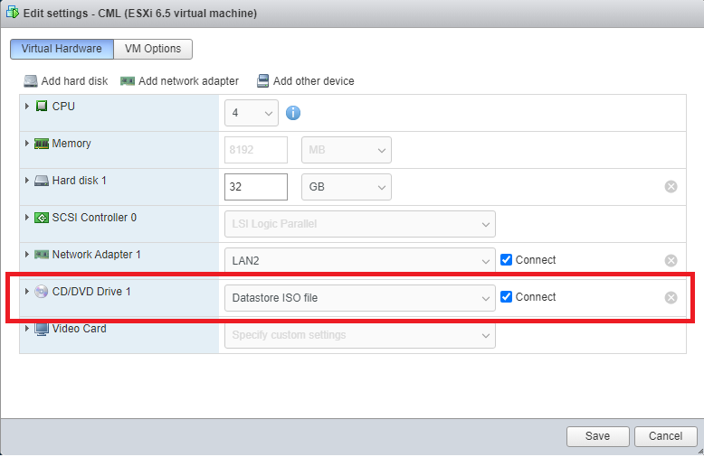
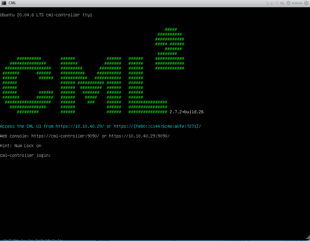
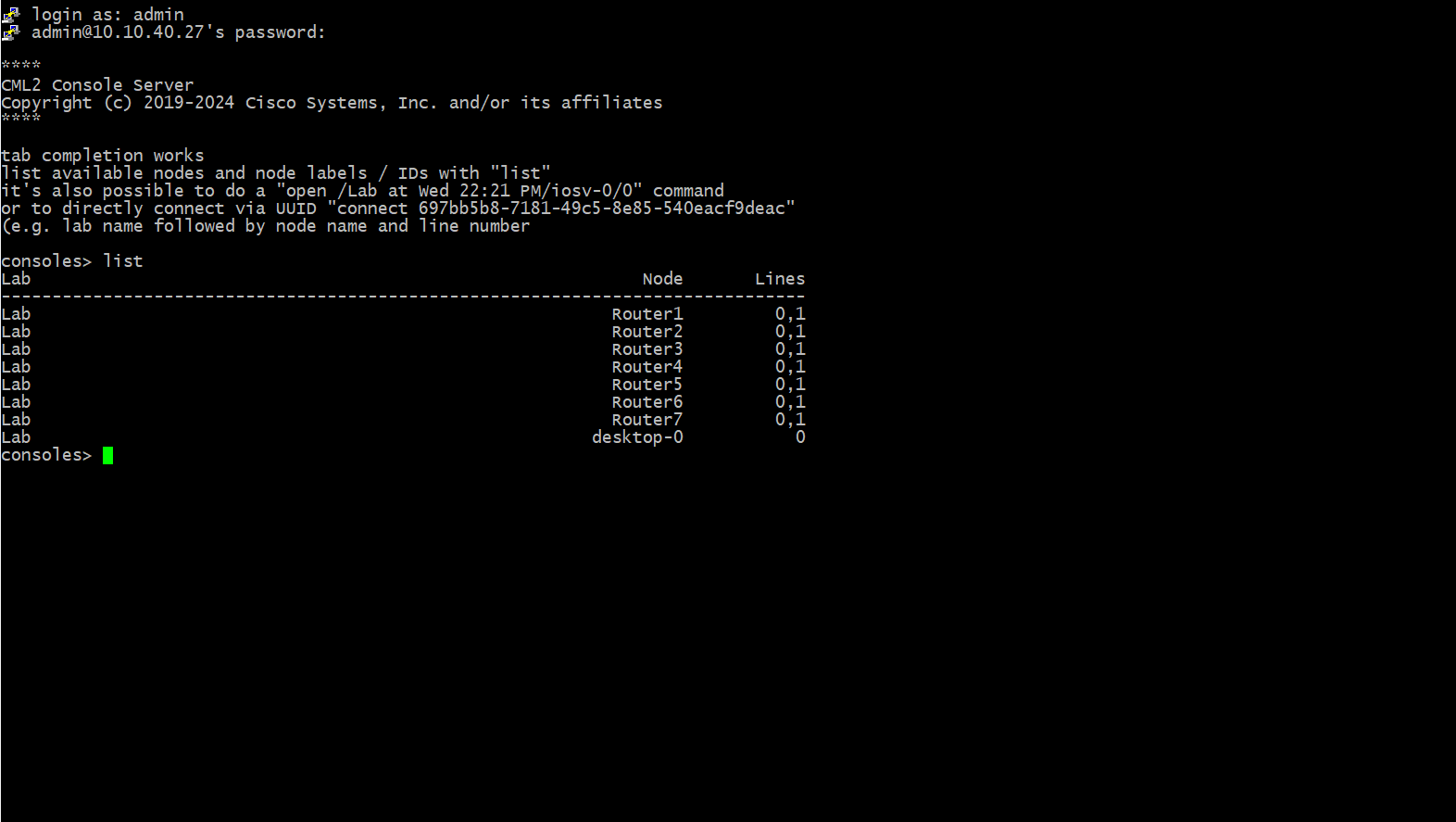
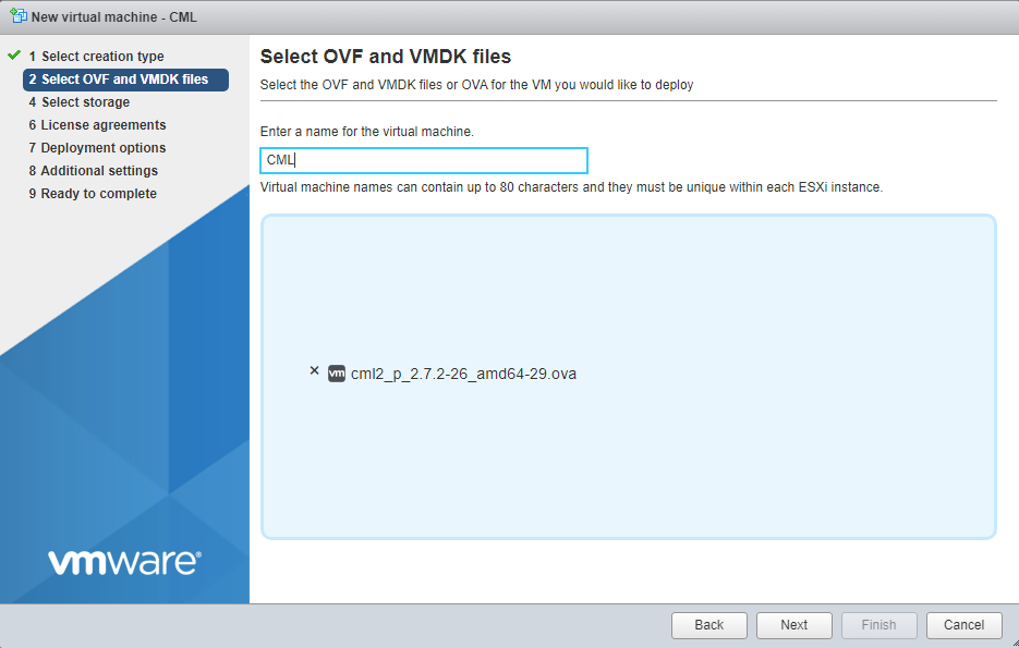
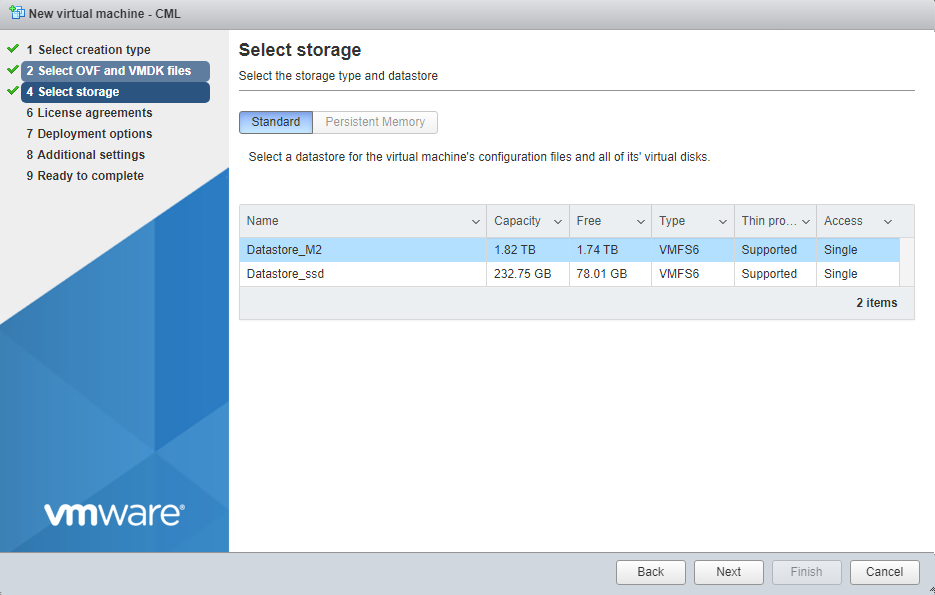
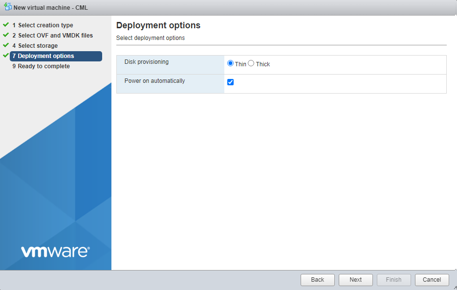
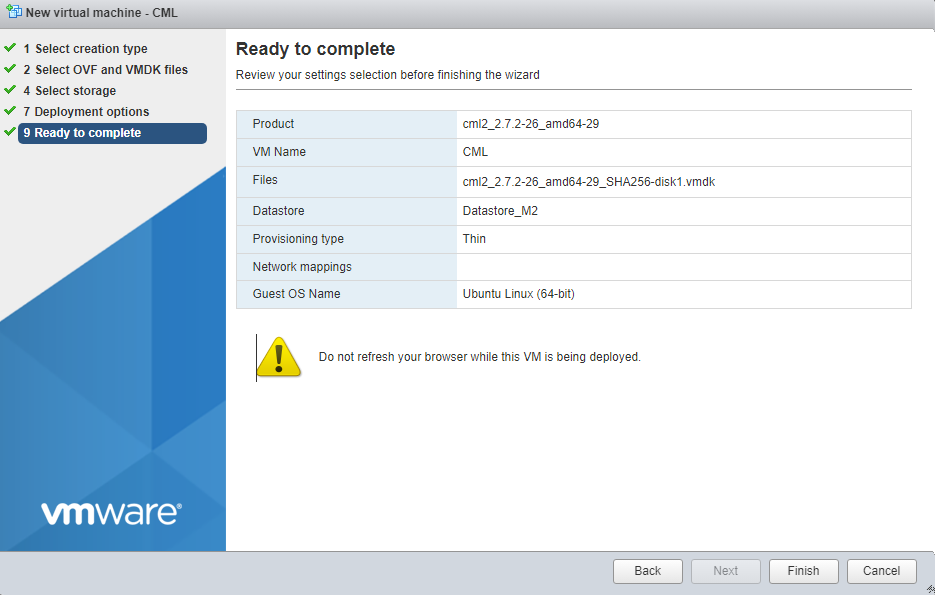
Last weekend I decided to try Cisco’s Modeling Labs (CML). This is Cisco’s network virtualization platform comparable to GNS3 or EVE-NG. It replaced an older Cisco product called VIRL (Virtual Internet Routing Lab), offering more features and improved performance.
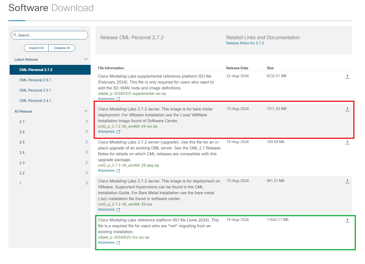
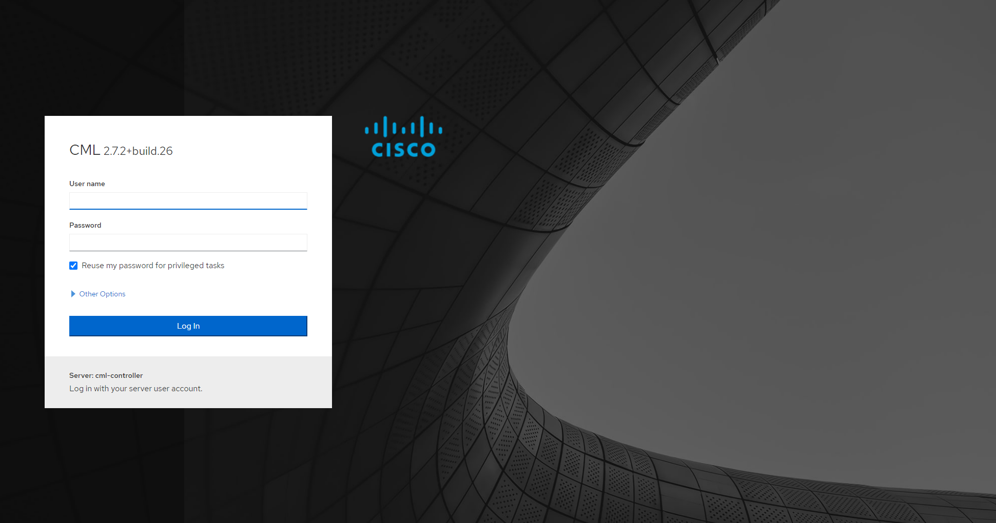
I have quite a lot of experience with both EVE-NG and GNS3, so I’m curious to see how CML will compare.

In this article we go over the following steps:

Getting started

I went with the option of installing CML on my ESXi server.
This installation will cover a fresh install on VMware ESXi using the CML .OVA file. 
Some useful links before we get started:

CML information:
https://www.cisco.com/c/en/us/products/cloud-systems-management/modeling-labs/index.html

CML Licensing:
https://learningnetworkstore.cisco.com/cisco-modeling-labs-personal/cisco-modeling-labs-personal/CML-PERSONAL.html

Software download:
https://software.cisco.com/download/home/286290254/type/286290305/release/CML-Personal%202.7.2

We start by downloading two files from the software website. We need both of these for the install.

    1. The server installation file (either the OVA of the ISO).
    2. The reference platform ISO (this contains the router images that are used in CML).

VMware: Creating the CML Virtual Machine

1: The first step is registering the new Virtual Machine:

2: Give it a name and select the downloaded OVA: 3: Select the datastore: 4: Select your Deployment options: 6: Verify and finish. 

CML: Installing the server

Once the Virtual Machine is registered and and booted you can access the console.
From the console we will start the CML installation.

1: Splash screen:

2: Accept the EULA: 
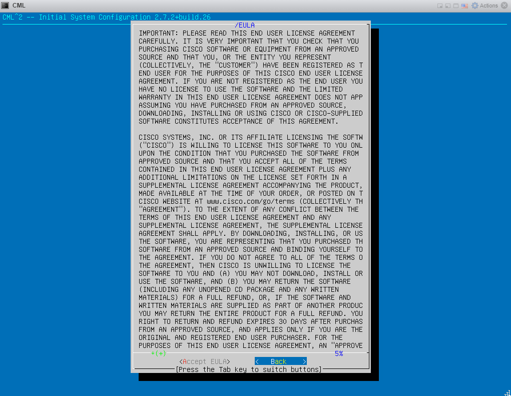
3: Information for accessing the Cockpit (port 9090):
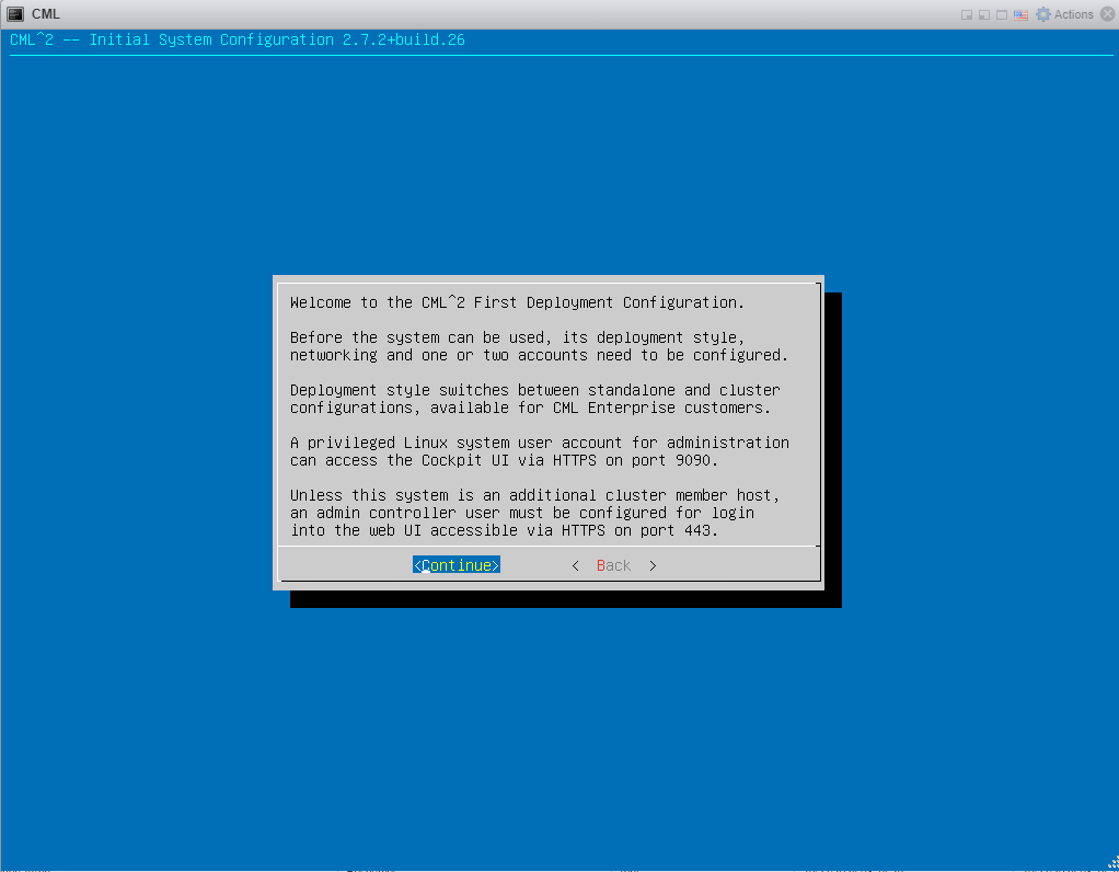
 4: Continue: 
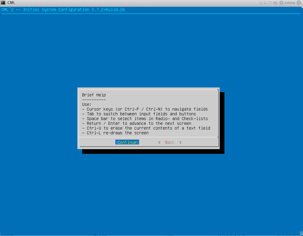
5: Continue with standalone all-in-one deployment.: 
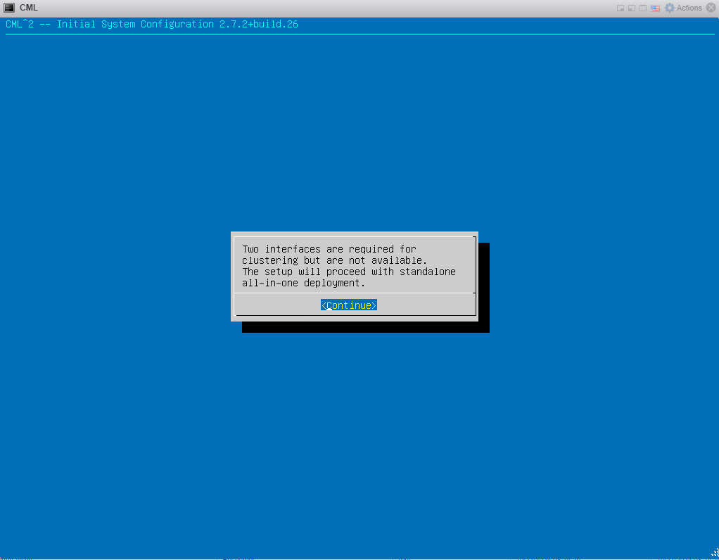
6: Enter the hostname: 
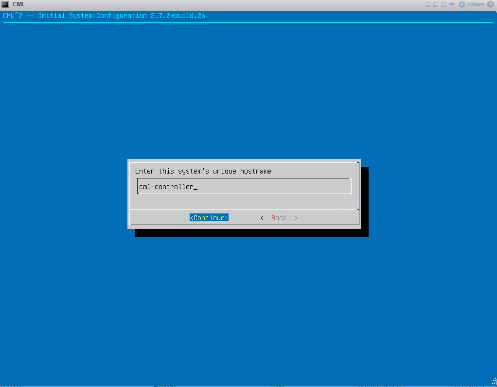
7: Create a system user: 
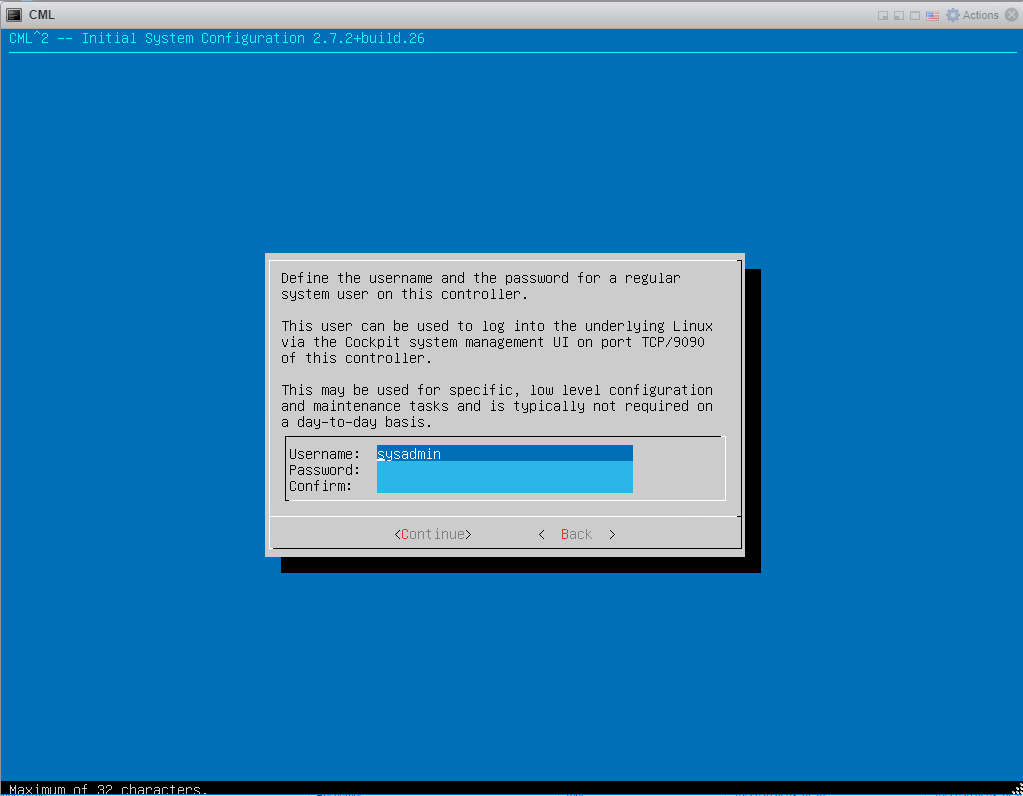
8: Create the admin user:
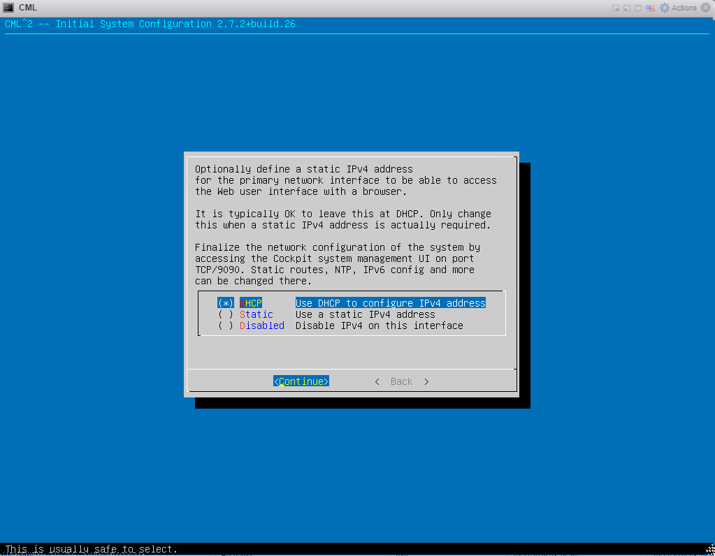
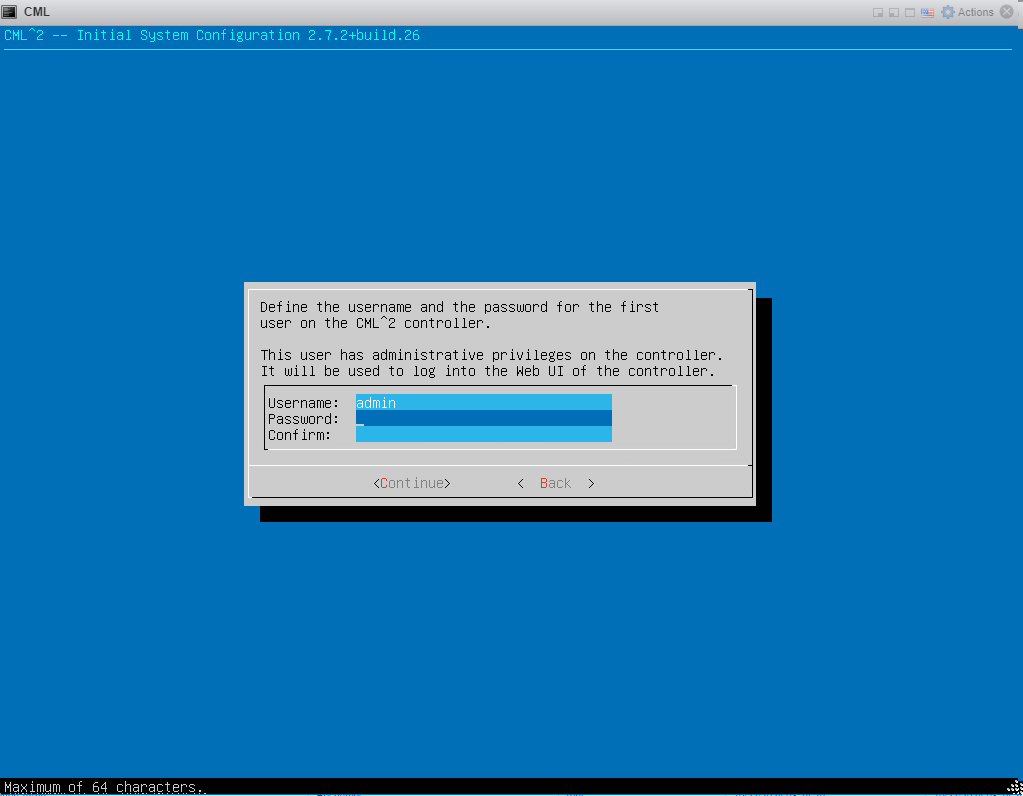
 9: IP addressing:
IMPORTANT:
10: Attach the reference ISO file as CD/DVD Drive in VMware by editing the Virtual Machine.
      The ISO is used to copy the router images/nodes into CML. 


11: Done!

You can now access CML via https://<IP> or access the administration cockpit via https://<IP>:9090

Expanding the vCPU, Memory and Disk size in CML

If you used the OVA file the Virtual Machine is configured with the following specs:

    • 4 vCPU’s
    • 8GB memory
    • 32 GB Harddisk

This works fine for basics lab, but I’d like to give the machine a little more power.
Increasing the vCPUs and Memory is fairly straightforward by editing the Virtual Machine’s hardware settings:

Expanding the virtual hard disk requires extra steps in the System Administration Cockpit which will we cover later.
First we add another 32GB to the virtual hard disk.


To allocate this extra 32GB we need to access the CML System Administration Cockpit.

CML System Administration Cockpit

When you need to access the System Administration Cockpit it will be available on: 

https://<CML-IP>:9090

From there we can log in using the system account we created during the installation.

1: Login to the System administration Cockpit:

2: From navigation pane open “Storage”:

3: On the top right open the Disk:

4: Add the new volume with the + button:

5:  Add the new allocated space:

6: The new Virtual Disk is added:

7: Use the new space to “Grow” your filesystem:

8: Select the size (everything) of the new volume you want to use:

9: Done!


Access your lab’s nodes via Putty / SecureCRT

Once you are logged into your CML environment making a new lab and adding the nodes is pretty straightforward. Accessing your nodes can be done with the build-in console. However accessing your nodes via an external client like Putty or SecureCRT is a little less intuitive. 
There are several ways to access your nodes; 

    1. CML Breakout Tool
      1. The Breakout Tool gives you local access to consoles and graphical interfaces of VMs running in a remote lab. The telnet protocol is used for console access, and VNC protocol is used for graphics-capable VMs. The Breakout Tool is a single executable file that you run on the command line. It provides a kind of proxy connection from the local machine, where the tool has been configured and started, to the nodes in the lab simulation. Once you install it, you can configure the Breakout Tool using a web interface that is accessible via the localhost (i.e., 127.0.0.1or [::1]) or loopback address on port 8080 by default. The port and listen address and the CML server’s URL can be configured via command line options or the tool’s configuration file (config.yaml). Using the Breakout Tool, you can use your favorite terminal emulator app to connect to your nodes’ consoles on configurable local ports.
        https://developer.cisco.com/docs/modeling-labs/breakout-tool-overview/
    2. Opening the console via an SSH session on the CML Server. 

I’ve used the second option and here are the steps to do it.

TestLab

I’ve created an MPLS test lab with the name “Lab” which contains 7 routers. The nodes are easily accessible via the build-in console but I want to connect using an external client without creating a proxy.

1: First we need to log into the CML server with SSH and find the console lines using the “list” command.
The output gives us the Lab name, the Node names, and the available lines. We need these in step 2.

2: Open the available consoles using the “open” command. 
The format will be “open /LabName/NodeName/LineNumber” and it is case sensitive.
 In my lab the command to open the console of Router1 is: open /Lab/Router1/0

3: Add the syntax as a remote command to your Putty session configuration for quick access.
Once we know the names we can add commands for each console to our saved sessions.

This will open an SSH session to your CML server and immediately open the console you configure. 
I’ve created several saved sessions for each router’s console for quick access.

350-501 Service Provider Core Resources


CCNP SPCOR 350-501 Official Cert Guide ( Release December 2024 )

https://www.amazon.com/CCNP-SPCOR-350-501-Official-Guide/dp/0135324807
No Ciscopress link yet.

SPCOR Cisco study Materials
https://learningnetwork.cisco.com/s/learning-plan-detail-standard?ltui__urlRecordId=a1c3i000003OvP0AAK&ltui__urlRedirect=learning-plan-detail-standard

SPCOR Cisco Official Learning Matrix  
https://learningcontent.cisco.com/documents/marketing/exam-topics/CCNP_SP_v1.0_Learning_Matrix.xlsx

 
SPCOR Videocourses
Luc de Ghein’s MPLS Fundamentals:
https://www.oreilly.com/library/view/mpls-fundamentals/9780134675398/

Nick Russo’s pluralsight courses.
https://www.pluralsight.com/authors/nick-russo
https://www.pluralsight.com/courses/cisco-service-provider-spcor-350-501-intro-cert
https://www.pluralsight.com/courses/cisco-multiprotocol-label-switching-implementing

INE.com:
https://my.ine.com/Networking/learning-paths/83c88b88-9041-4079-b913-2bd0474dae26/service-provider-core-exam-350-501-spcor

INE Live Webinar: Understanding Inter-AS L3VPN – Option A/B/C
https://www.youtube.com/watch?v=wT0eQPMj2Ck

CBTnuggets:
https://www.cbtnuggets.com/it-training/cisco/ccnp-service-provider-core


SPCOR Unofficial Studyguide
https://ccnp-sp.gitbook.io/studyguide

This study guide reads as more of a lab workbook than a textbook. I would highly recommend labbing along with each section. Each article typically starts with some background information and theory on the topic. You will then see a “Lab” section that contains a topology diagram and a code block with startup configs, which you can use to quickly build your own lab and follow along.

SPCOR Cisco Live PDFs
https://red9.nl/ccnp-service-provider-350-501-spcor-study-materials/

The CCNP Service Provider v1.0 Learning Matrix for the 350-501 SPCOR training references a lot of Cisco Live presentations. Unfortunately almost all links are broken at the time of writing this post. I’ve been able to find all except one of the presentations from all over the internet from a mix of AD infested presentation sharing sites.
Here they are, straight up linked PDFs to save you from the waste of time

IOS-XR Workbook
https://www.fryguy.net/wp-content/uploads/2013/03/Cisco-IOS-XR-Introduction-Ver-1.pdf

Cisco Press Books/Video
https://www.ciscopress.com/store/ip-routing-on-cisco-ios-ios-xe-and-ios-xr-an-essential-9781587144233
https://www.ciscopress.com/store/mpls-fundamentals-9781587051975
https://www.ciscopress.com/store/troubleshooting-bgp-a-practical-guide-to-understanding-9781587144646
https://www.ciscopress.com/store/bgp-troubleshooting-livelessons-9780134582870
https://www.ciscopress.com/store/bgp-design-and-implementation-paperback-9781587144707
https://www.ciscopress.com/store/end-to-end-qos-network-design-quality-of-service-for-9780133116106
https://www.ciscopress.com/store/qos-for-ip-mpls-networks-9780133434996
https://www.ciscopress.com/store/layer-2-vpn-architectures-9781587051685

SPCOR Roadmap
https://learningnetwork.cisco.com/s/cisco-certification-roadmaps?tabset-4a075=a9b02
SPCOR V1.1 will go live on 20 september 2024.


A.I. generated network diagrams

Today I had some fun with A.I. trying to generate network diagrams.

I asked an untrained A.I. model to generate “a simple MPLS topology” for my study notes. While the image looked like a computer network it still had many incoherent additions.

For the second image I used the prompt “a diagram explaining the difference between MPLS P, PE and CE notes”.


It will be interesting to see if we can learn the model to generate better topologies and streamline documentation.

[QoL] Uploading files to Cisco TAC via CXD

Uploading files to a Cisco TAC case.

Have you ever needed to upload large (log)files from an appliance to a Cisco TAC?

Troubleshooting DNA-Center for example usually involves creating Root Cause Analysis (RCA) files which can be well over 1GB. After generating the files we have to copy them from the controller and either mail them to the case, or upload them via the webinterface with the Case File Uploader. Both of these options require additional steps of copying and transferring. 

Customer eXperience Drive.

There is an easier way to upload the files directly from the controller using the Customer eXperience Drive (CXD).

The Customer eXperience Drive (CXD) is a multi-protocol file upload service with no limitation on the uploaded file size. It allows Cisco customers with active Service Requests (SRs) to upload data directly to a case using a unique set of credentials created per SR. The protocols supported by CXD are natively supported by Cisco products which allows for uploading directly from Cisco devices to SRs.

You will need the following things;

  • Service Request Number
  • CXD Token

To generate the CXD Token complete these steps:

Step 1   Log in to SCM.
Step 2   Open the case you would like to get the upload token for.
Step 3   Click the Attachments tab.
Step 4   Click Generate Token. Once the token is generated it will be displayed next to the Generate Token button.

Uploading files using CURL

Once we have the SR number (SR60000000) and the token (aaaabbbbccccdddd) we can use that to upload directly from a controller. We can transfer the file with our SR credentials to https://cxd.cisco.com/home/ and the file will be automatically added to the case.

CURL without a proxy:

  • curl -T “[path/to/file]/[file]” -u 60000000:aaaabbbbccccdddd https://cxd.cisco.com/home/

CURL with a proxy:

  • curl -T “[path/to/file]/[file]” -x http://[proxy:8080] -u 60000000:aaaabbbbccccdddd https://cxd.cisco.com/home/

Sample Python Code to use the PUT API

Note that the following code assumes the file is stored in the same path you are running it from.

import requests
from requests.auth import HTTPBasicAuth
url = 'https://cxd.cisco.com/home/'
username = 'SR Number'
password = 'Upload Token'
auth = HTTPBasicAuth(username, password)
filename = 'showtech.txt'
f = open(filename, 'rb')
r = requests.put(url + filename, f, auth=auth, verify=False)
r.close()
f.close()
if r.status_code == 201:
    print("File Uploaded Successfully")

Enjoy your no limit uploads!

LAB IX – RIPv2 -> OSPF Case Study

Building a use case from the CCDP FLG:

Topology:

  • Each site has two links to their HQ (top) via WAN (Prio) and Internet ( backup ).
  • Internet and WAN connectivity goes over multipoint GRE tunnels to the sites with static NHRP mappings.
  • Cost of Internet links are increased so they’re used as backup links.
  • Backbone area configured over WAN and Internet

Building the LAB:

OSPF Design

Building the Backbone:

Adding the tunnel interface and NHRP mappings on the WAN Hub Router (R1):

And we have some routing on the Hubs:

[DC] Cloud Computing

Basic cloud computing

  • Essential Characteristics
    • Broad network access
    • Rapid elasticity
    • Measured Service
    • On-demand Self-service
    • Resource pooling
  • Service Models
    • SaaS – Software as a Service
    • PaaS – Platform as a Service
    • IaaS – Infrastructure as a Service
  • Deployment Models
    • Public
      • Provisitioned for open use by the general public
    • Private
      • Cloud for the exclusive use by a single organization
      • Managed by IT or thirdparty
      • on-premise or off-premise
    • Hybrid
      • Two or more cloud infrastructures combined
    • Community
      • Multiple organisations combined

What is an API

  • A precise specification written by providers of a service
  • You must follow the specification when using that service
  • An API decribes what functionality is available, how ti must be used and what formats it will accept as input or return as output

(more…)

[DC] ACI and APIC

ACI > Contructs

Tenant VDC
Context VRF
Bridge domain Subnet / SVI
EPG Broadcast domain / VLAN
Contract ACL
L2 External EPG 802.1Q trunk
L3 External EPG L3 Routed link

Fundamentals:

  • Open and Secure
  • Apps and Infrastructure
  • Physical and Virtual
  • On-Site and Cloud

Bringing up the Fabric:

  • Physical requirements
    • Power
    • Cabling + mgmt0
    • Rack and Stack
  • Power on/Connect to APICs
    • How many APICs
    • Fabric Name
    • Admin Password
    • Setup Fabric Network ( IP & VLAN)
  • Log into the APIC (HTTP out of band)
    • NTP
    • Route Reflectors
    • MGMT IP Fabric
    • Leaf and Spine Name/#

Fabric Discovery

  • Zero touch fabric, the controller does everything
  • APIC uses LLDP to get information about the leaf switches it’s connected to
  • First the leaf is dicovered and will be named (101)
  • Then the Spine is connected and named  (201)
  • Then the leafs are discovered (103,104)

(more…)

[DC] Datacenter Interconnects (DCI, OTV)

Distributed Data center Goals

  • Ensure business continuity
  • Distributed applications
  • Seamless workload mobility
  • Maximize compute resources

Challenges in traditional Layer 2 VPN:

  • Flooding Behavior
    • Unknown unicast for mac propagation
    • Unicast Flooding reaches all sites
  • Pseudo-wire Maintenance
    • Full mesh of Pseudo-wire is complex
    • Head-End replication is a common problem
  • Multi-Homing
    • Requires additional protocols and extends STP
    • Malfunctions impact multipe sites

(more…)