Cisco Live EMEA 2026 – Amsterdam
Introduction
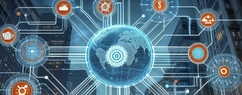
Cisco Live was an intense and inspiring week filled with deep technical learning and great people. I focused on topics like Design, Certifications, SD-Access, Catalyst Center, AI, security, high availability, Wi-Fi, IPv6, and service provider technologies. Hands-on labs and interactive sessions made the experience practical, not just theoretical. This year I also joined feedback sessions, community events, Meet the Engineer, and interactive breakouts.
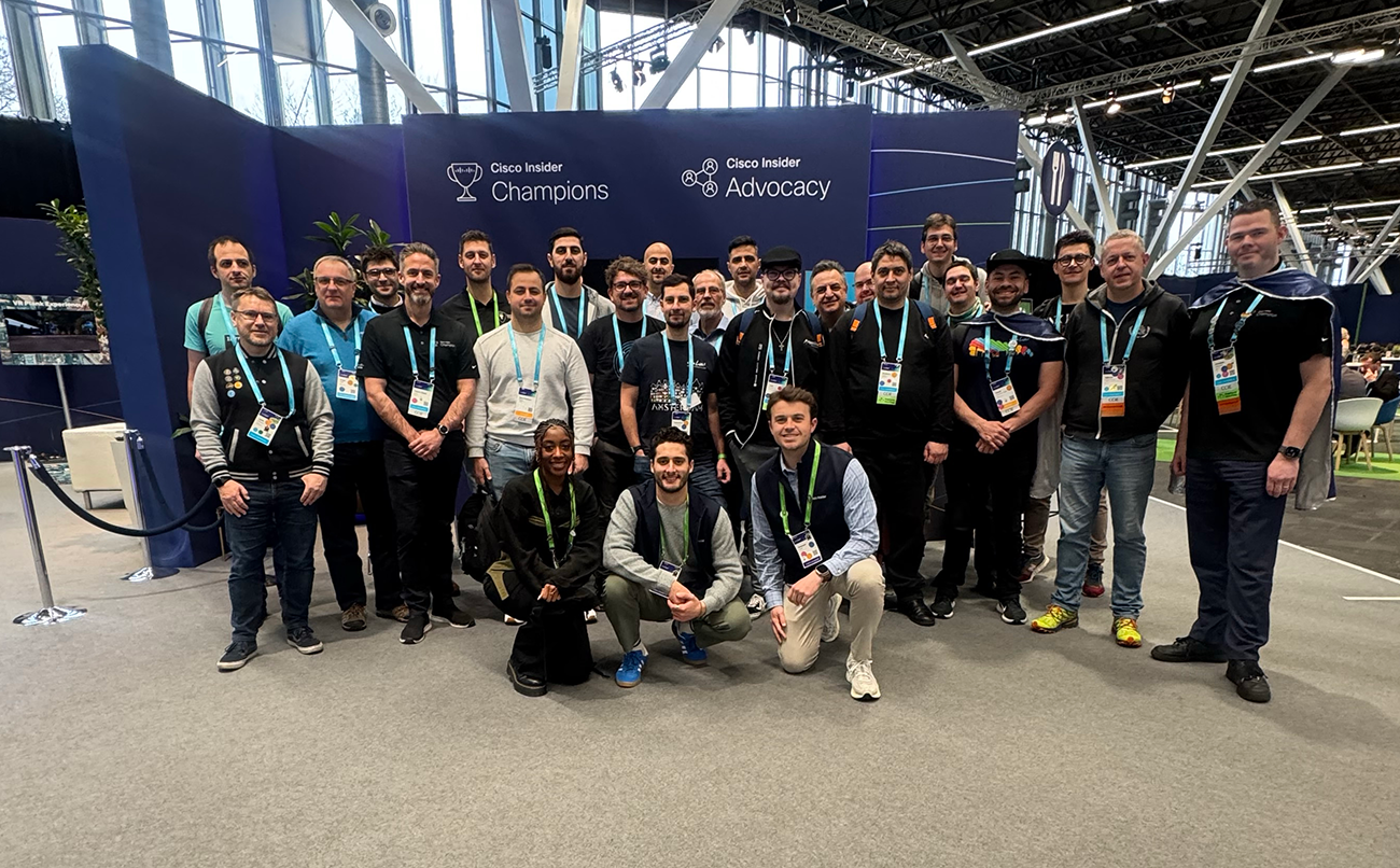
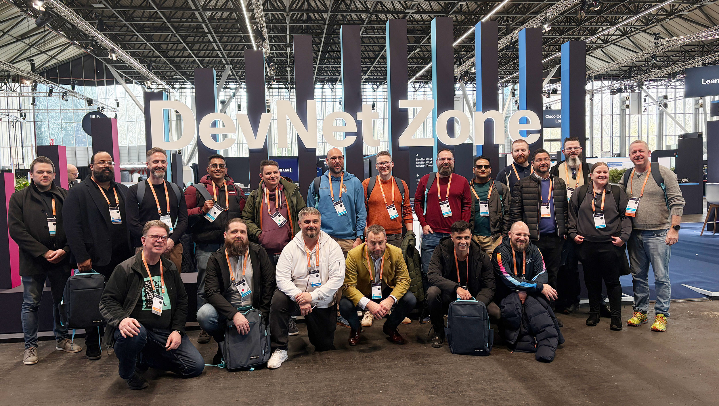
Cisco Champions
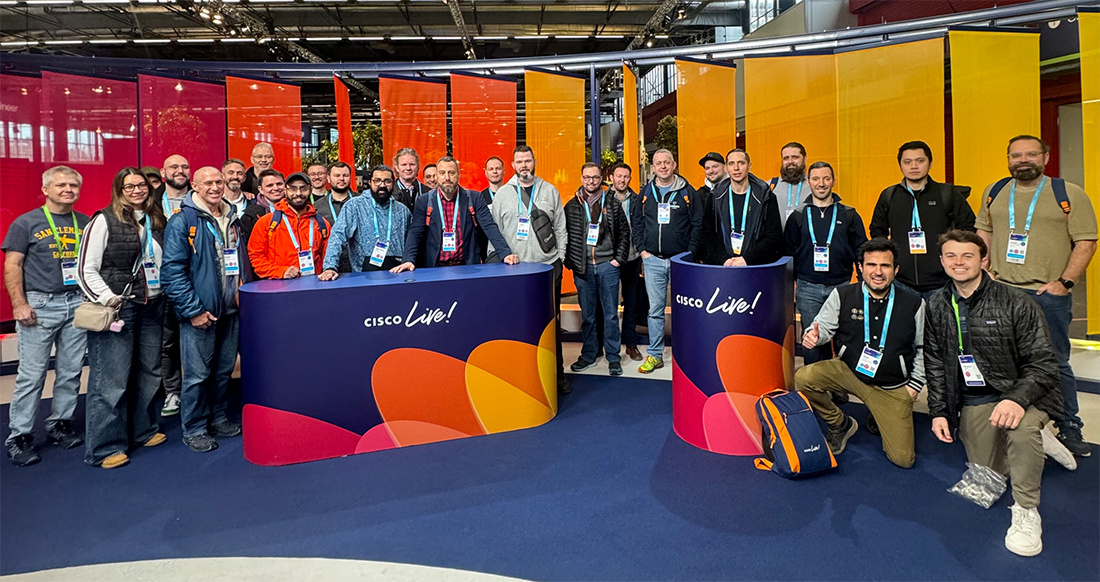
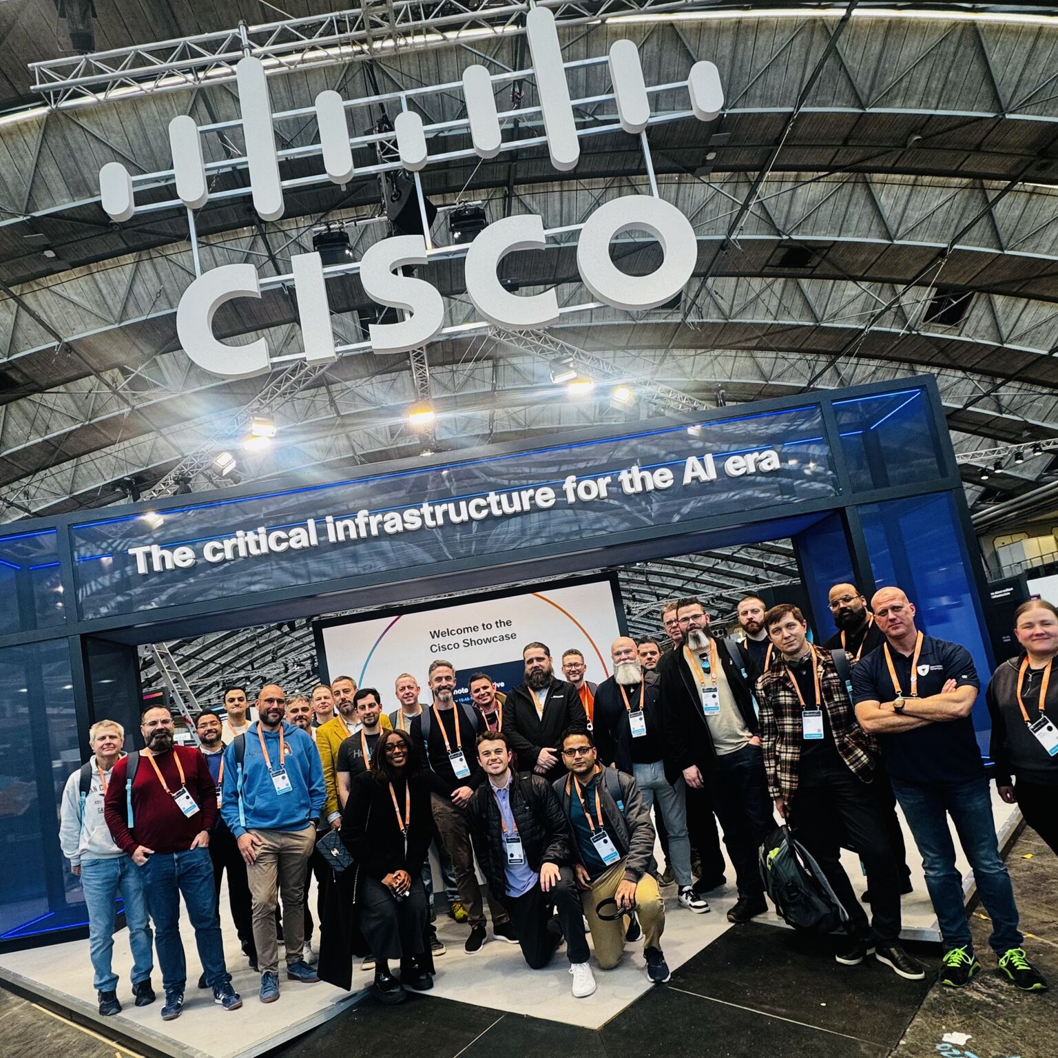
As a Cisco Champion, I also connected with an amazing community and met engineers from all over the world. The hallway conversations, meetups, and shared experiences were just as valuable as the sessions themselves.
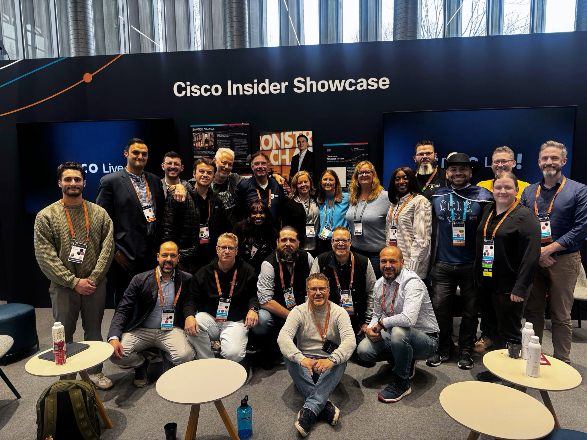
A huge thank you to the Cisco Insider program managers for organizing early access, exclusive sessions, and so many extra activities. Their efforts truly elevated the entire Cisco Live experience and made everything run smoothly for us. Having those additional opportunities provided deeper insights and more meaningful interactions throughout the week.
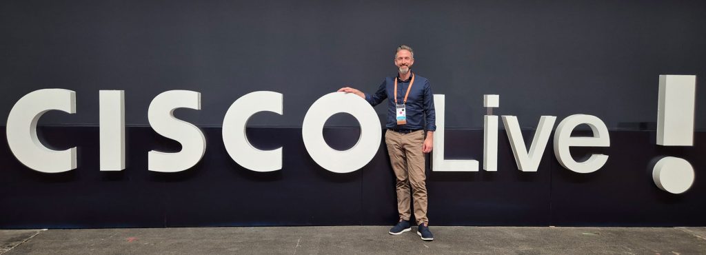
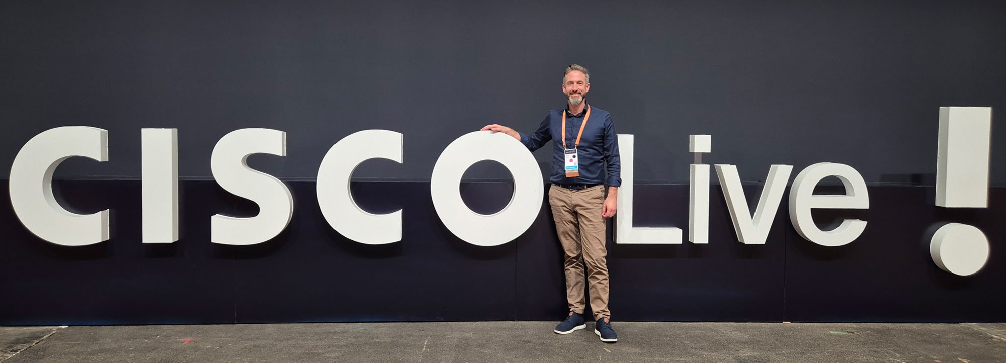
Impressions